Property Editors
Standard properties are shown in bold. Advanced properties are shown in italics.
Displayed fields can be sorted in one of two ways by using the following buttons:
-
 Categorized
 -
 Alphabetical
Some properties are only shown for specific devices.
Initially only basic fields are shown. To reveal all fields, click ![]() Advanced.
Advanced.
To filter the list, enter all or part of a property name in the ![]() box.
box.
| For all other property editor descriptions, refer to the Ethernet Gateways Commissioning Guide. |
Device Properties
This editor displays device information and basic device configuration properties in the following categories.
Device Identification
| Property | Description |
|---|---|
DUID |
Device Unique Identifier |
Device Name |
Used to identify the device. |
Location |
The physical location of the device. |
Description |
Other identifying information for the device. |
Box number |
Physical address used for identification by the Dynalite system. |
Serial number |
The serial number of the device. |
Device location sequence |
Identifies devices sequentially on a series network, not required. |
System designer device number |
|
IPv4 Address |
32-bit network address expressed in decimal. (For device with Ethernet port) |
IPv6 Address |
128-bit network address expressed in hexadecimal. 32 hexadecimal numbers. (For device with Ethernet port) |
Product Information
| Property | Description |
|---|---|
Product name |
These fields are populated automatically, and identify the product type, hardware, firmware, and bootloader versions. |
Product category |
|
Product type |
|
Device code |
|
PCB assembly |
|
Model ID |
|
Firmware version |
|
Bootloader version |
|
Has RTC |
Device has a built-in real-time clock. True or False. |
Number of circuit breakers |
Device Status
| Property | Description |
|---|---|
Device status list |
These fields are populated automatically, and show information about the device creation, modification and current status. |
Date time created |
|
Date time modified |
|
Date time memory loaded |
|
Date time memory saved |
|
Date time task compiled |
|
DyNet bus voltage |
Start-up Settings
| Property | Description |
|---|---|
Start delay (rounded to 10 ms) |
Delay after start-up before sending sign-on message. |
Sign on at start up |
Send sign-on message after start delay. |
Start-up Preset |
Device loads this preset on startup (default: Previous Preset). |
Comms
| Property | Description |
|---|---|
Area zero transmit |
Enable all areas messages for diagnostic use. |
Default to DyNet2 |
Sets the default communication protocol to DyNet2. |
Delay (milliseconds) |
The delay between sending messages. (default: 10ms) |
DMX origin channel |
Disabled when not using DMX512 communication on the RS-485 bus. Otherwise, sets the DMX start channel. Minimum value = 1. Maximum value = 512. |
DyNet Watchdog
| Property | Description |
|---|---|
Watchdog |
If Enabled, device listens for a periodic DyNet message to ensure that it is connected to the network. |
Obey messages after timeout |
If True, device continues to obey DyNet commands after a Watchdog timeout. |
Watchdog run at startup |
If True, device checks that it is online at startup. |
Watchdog timeout (rounded to 10 ms) |
The maximum time the device waits for a Watchdog message before assuming it is offline. |
Watchdog Preset |
If the device times out, it recalls this preset. |
Features
| Property | Description |
|---|---|
Enable area link for optional opcodes |
Affects certain DyNet messages that may ignore area linking by default. |
Include controller in Localise By Search |
If Disabled, the controller’s outputs are excluded from Localise By Search. |
Manual override keypad |
Enable or Disable the channel/DALI line override buttons on the front of the controller. |
DALI
| Property | Description | ||
|---|---|---|---|
DALI start delay |
The time between drivers being turned on and the first message from the controller. The DALI standard requires drivers to accept DALI messages within 680ms of powering up.
|
||
Enable DALI collision detection |
If Enabled, the device analyzes incoming and outgoing packets to avoid collisions in DALI communication. |
||
Use DALI Broadcast |
DDBC120-DALI only: Sets the DALI output to DALI broadcast mode. |
||
Enable DALI status polling and driver failure alarms |
If True, the controller monitors the status of its known drivers and reports any changes to SB/SM. |
||
Enable DALI device status polling and failure alarms |
If True, the controller monitors the status of its known DALI devices and reports any changes to SB/SM. |
||
Enable silent (auto) DALI enumeration |
If True, the controller finds and addresses all connected drivers when first energized, saving commissioning time. |
||
Enable automatic DALI driver replacement |
If True, the controller automatically self-repairs the DALI network when a single driver is replaced, updating the offline driver to the newly discovered driver and reusing the same short address. This feature requires Enable DALI status polling and driver failure alarms and Enable silent (auto) DALI enumeration both set to True. |
||
Enable Mexican wave |
If False (default), the controller sends DALI group address messages to multiple drivers. |
||
Write DALI power on level |
If True, enables the DALI power-on level, color type, and color temperature options below. |
||
DALI power on level (%) |
The initial light level (%) when a DALI driver is energized. Select Previous level or enter a value. |
||
DALI power on colour type |
The initial color type when a DALI driver is energized (Colour Temperature (specified below), RGBWAF, or None). |
||
DALI power on colour temperature |
The initial color temperature when a DALI driver is energized. |
||
Write DALI system failure level |
If True, enables the DALI system failure level, color type, and color temperature options below. |
||
DALI system failure level (%) |
Light level (%) when the DALI driver cannot communicate over DALI. |
||
DALI system failure colour type |
Color type when the DALI driver cannot communicate over DALI (Colour Temperature (specified below), RGBWAF, or None). |
||
DALI system failure colour temperature |
Color temperature when the DALI driver cannot communicate over DALI. |
||
Invert DALI Relay Universe (1, 2, or 3) |
Set to True if relay is driving a Normally Closed contactor. |
UL 924
| Property | Description |
|---|---|
UL924 enabled |
If Enabled, the controller responds to a UL 924 trigger by recalling its Emergency system preset, and stops responding to other commands while in emergency mode until the UL 924 input is reset. |
Trigger emergency |
Determines if the Emergency preset is triggered by the UL 924 dry contact switch becoming Open or Closed. |
Deactivation delay |
Delay after the UL 924 trigger is deactivated before the controller reverts to normal operation. |
Use AUX input for UL924 |
If Enabled, the AUX input becomes a UL 924 input. |
DALI Diagnostics (DDBC320-DALI only)
This editor provides a fast way to detect installation issues on the DALI bus.
| System Builder requires a Technician license to access the DALI Diagnostics editor. |
DALI communications are negatively affected by ringing and voltage drop on the DALI bus. Ringing and voltage drop symptoms appear as drivers/devices with intermittent communication and temperamental commissioning onsite but may work well on a test bench. They can exhibit one-way communication, responding to broadcast and direct messages but not responding when queried.
-
Ringing is a voltage oscillation caused by self-resonance of the line responding to the signal level change (there will always be some ringing) that hinders communications to the point where a receiving device is no longer able to interpret incoming messages.
-
Voltage drop is a decrease in voltage along the DALI line due to conductor resistance. A voltage drop on the line of more than 2V when measured between the DALI controller and a driver/device can cause communication loss. DALI devices communicate by alternating voltage levels across the line between high and low.
A driver/device at the lowest voltage point on the bus may change the voltage by the correct amount, but this may not be low enough at the receiving device, because there is less voltage drop at that location.
Ideally the low voltage level should be less than 3V during communication to make the system more tolerant of voltage drop. Some drivers/devices from different manufacturers may be more susceptible to voltage drop than others.
-
Star or mixed topology
-
Long cable runs
-
Low cable gauge
-
Coiled up cable
-
Type and quantity of drivers/devices
-
Distance from DALI power supply to drivers/devices
-
Poor electrical terminations
-
In System view, select a DDBC320-DALI and open the DALI Diagnostics editor. Initially SB shows a
 icon next to each DALI line/universe as it does not yet know the network status.
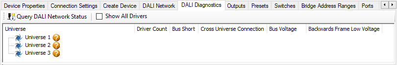
-
Click
 Query DALI Network Status.
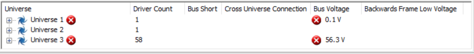
If no issues are detected, the result shows the number of drivers on the bus and the bus voltage.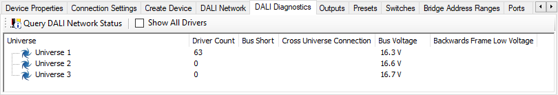
-
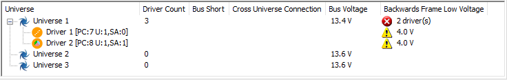
Click + and – to next to the universe to expand and collapse the driver list.
Tick the Show All Drivers checkbox to show all driver addresses.
The measured Backwards Frame Low Voltage value is shown for each driver.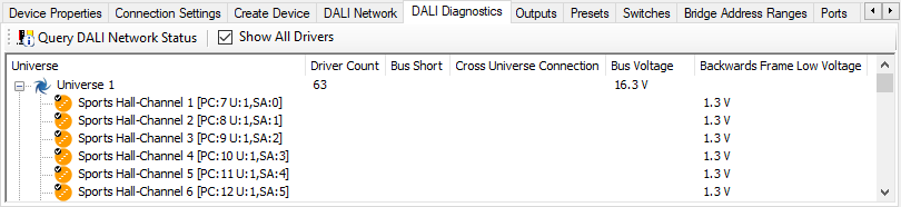
-
If errors are detected, refer to DALI Bus Issues below.
-
If you change the wiring, rerun the diagnostics to see if the fault is cleared.
The following issues can be detected:
DALI Bus Issues
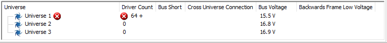
Universe Full
More than 64 drivers are connected to the DALI bus.
-
Reduce the number of drivers as required.
-
Flash the universe and count the number of drivers connected to the DALI bus.
-
If you are trying to replace a driver in a full line/universe, open the Outputs tab and click the button (in the Clear DALI Address column) for the removed driver, then install the new driver and re-enumerate the universe.
-
Clear all offline uncommissioned drivers (in Area 1 and not assigned to a fixture icon).
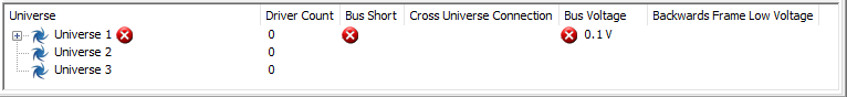
Bus Short
Short circuit across DA+ & DA-.
-
Find and remove the short circuit from the DALI wires.
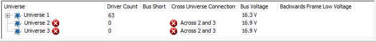
Cross Line/Universe Short
The DALI wires of two different outputs have been wired together.
-
Remove DA+ and DA- from one of the affected controller outputs and check for voltage on the removed wires. If you see a voltage, then it is coming from one the other outputs. Remove DA+ and DA- from another output. If the voltage disappears then you know that one of these wires is connected somewhere to the first bus/universe.
-
Split the network into shorter segments and connect a segment to the controller output. Flash each output to find where the DALI wire for one bus/universe has been connected to a wire from another bus/universe.
-
Correct the wiring.
DALI Bus Voltage
The DALI voltage is outside the acceptable range of 11.5V to 20.5V.
-
Disconnect the DALI load from the controller and check if supply voltage on the controller output is correct.
-
If the voltage is too low, it could be a faulty driver or short circuit on the bus. You may need to check the termination quality. Replace faulty drivers/devices and reduce the number of drivers and devices as per the table below.
Drivers
64
59
54
49
44
39
34
Devices
10
11
12
13
14
15
16
-
If the voltage is too high, another DALI power supply is incorrectly connected to the bus (or enabled, if SR type drivers).
Driver Communications Quality
The voltage of a message received back from a driver (Backwards Frame Voltage) exceeds 4V. A voltage of 3V to 4V may also indicate an issue.
-
Forwards and backwards communication in DALI are quite different. Measure bus voltage at remote end. Expect to see approximately 15V.
-
Fixtures with their own DALI power supply will also cause this issue. Remove other power supplies.
-
Check wiring and make sure it meets cable quality and length requirements.