Initial Setup
To complete the configuration process, you will need to consider the following factors:
-
Area climate specifications
-
Selection of areas to be controlled
-
Environmental and usage factors
-
User interface control buttons
-
Number and location of controllers (typically one per area)
-
Plant hardware interface, capacity, and limitations
-
Lag times between control signal and effect
-
Lower-energy solutions (window coverings, passive ventilation, etc.)
-
Control scheme to be used (PID/staged)
Add Device to the Job
When System Builder and the DDFCUC are both connected to the network, you can add the controller to the job by clicking ![]() Insert Devices from Network. To create an offline device, click
Insert Devices from Network. To create an offline device, click ![]() Insert Device from List.
Insert Device from List.
Create Areas and Channels
To establish default settings, area and channel must be assigned to each DDFCUC.
In Areas view, create an HVAC area and channel for the controller, then create additional channels as required for the fan and GPR outputs.
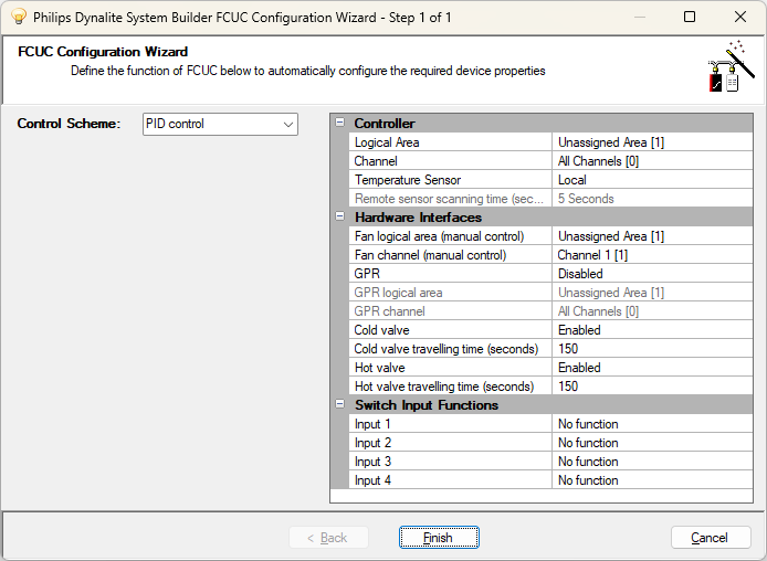
FCUC Configuration Wizard
This wizard simplifies initial setup by walking you through the main settings required by the controller. Regardless of whether you use the wizard, you can manually configure all settings and properties in the device’s System view editors.
-
Right-click the DDFCUC and select
 FCUC Configuration Wizard…, or select the DDFCUC and press Alt+W.
 -
Configure the properties for each section of the wizard and then click the button.
-
Click
 Save to Device (F12).
| If GPR is set to Heating or Cooling with the PID control scheme in effect, then the General Purpose Relay must be used for heating/cooling purposes and NOT the hot/cold water valve. |
| Property | Description |
|---|---|
Control Scheme |
PID control or Staged control |
Controller |
|
Logical Area |
Assigned area for plant control. |
Channel |
Assigned channel for plant control. |
Temperature Sensor |
Local (directly connected to the controller) or Remote (connected via the DyNet network). |
Remote sensor scanning time (seconds) |
Polling period for remote sensor (default: 5 Seconds). |
Hardware Interfaces |
|
Fan logical area (manual control) |
Assigned area for manual fan control. |
Fan channel (manual control) |
Assigned channel for manual fan control. |
GPR |
Disabled/Manual/Heating/Cooling. |
GPR logical area |
(Manual only) Assigned area for GPR output. |
GPR channel |
(Manual only) Assigned channel for GPR output. |
Cold valve |
Enabled/Disabled. |
Cold valve travelling time (seconds) |
As per plant manufacturer specifications. |
Hot valve |
Enabled/Disabled. |
Hot valve travelling time (seconds) |
As per plant manufacturer specifications. |
Switch Input Functions |
|
Input 1-4 |
|
In addition, the wizard sets the following default values:
-
For all logical addresses, set Join 0xFF and BLA Disabled.
-
Set all input switches' Logical Area/Channel to match the controller.
-
Set Cold/Hot valves configuration type to Floating.
-
Enable all Faults/Signals and set their Auto restart count to Infinite Restart Attempts.
-
All other properties will match the default (factory set) values.