Ethernet Bridge
Address Offsets
Each floor gateway is configured with a unique IP address and DyNet address offset for each spur (physical and logical address range, for example, 1000, 2000, 3000 etc.).
Logical address offsets in each EG enables reuse of area numbers (and use of common area numbers when required). The routing ensures that only systemwide and inter-spur communications are sent over the trunk. Intra-spur communications remain within the spur.
| A common logical range may also be added to other gateways (for example, areas 201 – 255) for logical messages to other floors. The Bridge Configuration Wizard will identify other gateways with common areas. Common areas create a lot of additional routing between the gateways. Only use common areas if you have a genuine need to control areas on different floors from a user interface/sensor on another floor. |
The diagram below shows different logical address range offsets on two spurs and a common logical address range shared by both spurs.
Physical address offsets in each EG enable it to maintain electrical isolation from the trunk while keeping intra-spur communication within the spur and allowing the reuse of device box numbers. The diagram below shows different physical address range offsets on two spurs and a common physical address range when using two EGs as a single spur.
Ethernet to RS-485
The EG acts as a bridge between Ethernet and RS-485 to establish a trunk-and-spur topology for efficient data transport. EGs are usually added to the SB job first to establish the Ethernet trunk, and then other devices are added under each EG to create the RS-485 spur subnetworks.
The EGs provides a way to isolate parts of the network by routing messages only for SM, common areas and devices on other spurs, over the trunk. In addition, EGs provide status polling, metric collection, area cascading, and scheduling features.
TCP connections can be secure or non-secure:
-
Non-secure connections can use a PDEG or PDDEG-S.
-
Secure connections must use a PDDEG-S.
To commission an EG as an Ethernet bridge, first plug the commissioning PC into a DyNet spur with an EG. Connect SB using a serial connection and add the EG to the job. Refer to Adding an EG over RS-485.
The EG can be precommissioned. However, ports and connection settings may require updating once installed onsite.
-
Select the EG from the Device tree.
-
In Device Properties > Device Identification, enter the Device name (this identifies the EG in SB).
-
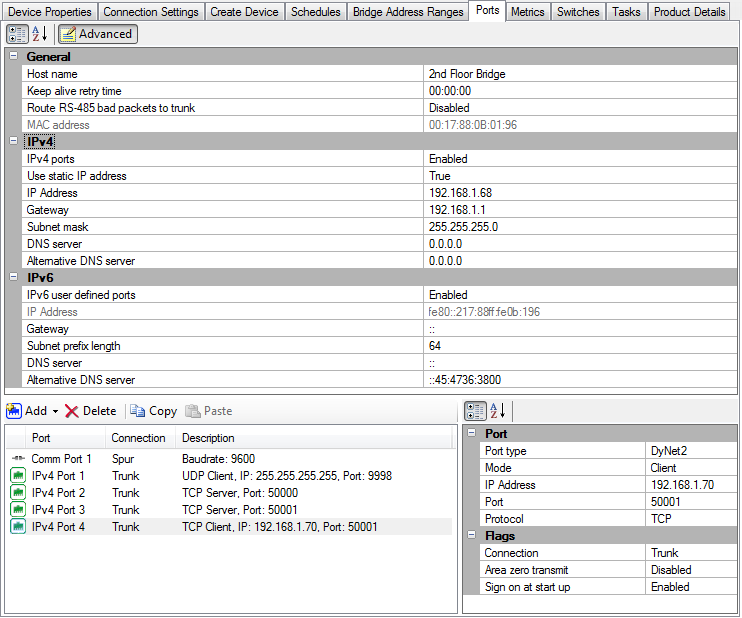
In the Ports editor, enter a Host name (this identifies the EG on the LAN).
-
Under IPv4 properties, set Static IP to True.
-
Enter the IP address for the EG.
-
In the Gateway property, enter the IP address of the router.
-
In the Subnet mask property, enter the subnet mask of the router (if different to the default value).
-
Repeat this procedure for every bridging EG in your system.
|
To create the required ports and routing rules for your EG, please run the |
-
Connect SB to the network via a serial RS-485 connection.
-
Right-click the EG in the device tree and select
 Bridge Configuration Wizard or press Alt+W.
 -
Select Ethernet to RS-485 Translation Gateway and click the button.
For precommissioning, untick the Connections checkbox. Trunk and inter-spur IP addresses can be added when connected on site. 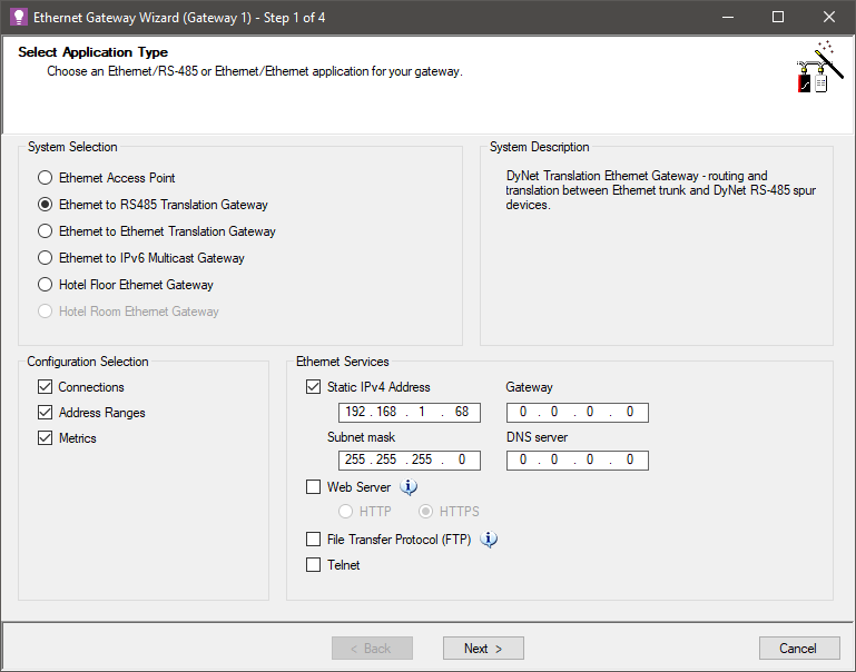
-
Set the Trunk Connection > Connection Type to TCPv4 on Port 50001.
Set the Inter-spur Connection > Connection Type to TCPv4 on Port 50003.
Click the button.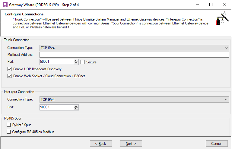
-
 Secure should be unticked. For secure gateway setup, refer to PDDEG-S Site CA Certificate and Secure Ethernet to RS-485 below.
 -
 Enable UDP Broadcast Discovery enables the UDP IPv4 discovery port (Port 9998) used by SB to find the bridges in the system (listed in the Connection Settings page under Ethernet Trunk Connection Settings). It also enables DynamicTouch access.
 -
 Enable WebSocket / Cloud Connection / BACnet enables WebSocket trunk connectivity for SB/SM, cloud connectivity for Dynalite Cloud, and BACnet for BMS integration.
 -
 DyNet2 Spur routes DyNet2 messages from the trunk onto a DyNet2 RS-485 spur.
 -
 Configure RS-485 as Modbus converts the RS-485 port from DyNet to Modbus for use with Modbus Power Meters
-
-
Click and enter Offset, Min and Max values.
-
Click and enter Offset, Min and Max values. Primary address Min value must be 1 or 0 (see note below).
-
OPTIONAL: Click again to enter address ranges that are common to multiple EGs. The range defined by the Min and Max values must not overlap with the other logical ranges.
SB lists the EG devices that it finds in the job that share common address ranges. The address ranges must match exactly.
-
Click the button.
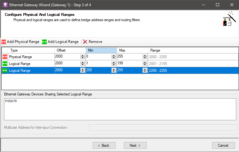
Do not use common areas unless you have a genuine need to control areas on different floors from a user interface/sensor on another floor. When finishing the wizard, it will ask if you want to automatically create the additional routing between the gateways with common areas. The primary logical range for the spur can also be changed to start from 0 if you want to allow for Area 0 (All Areas) messages to be sent from the trunk. You must enable the Area Zero Transmit property on the port record for the EG. Spur devices may require further configuration to support this. A common logical range enables the system to address areas that span multiple spurs. A common physical range enables devices to appear on a single spur when attached to different EGs. -
You can select the checkbox and enter different polling periods, if applicable or click the next button to accept the default metrics for devices and channels on the spur.
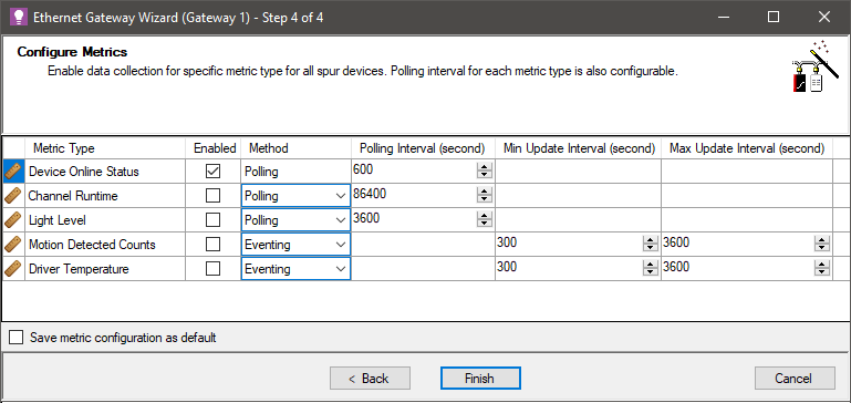
Ensure only necessary metrics are selected to minimize network traffic. -
Click the button.
-
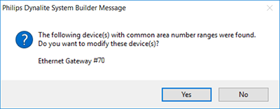
A popup message indicates the other EGs that must have their settings saved.
-
Click .
-
Press F12 or click
 Save to Device.
 -
Repeat this procedure for every EG bridge in your system.
-
Click File >
 Save to save the job to your PC.
| For security reasons, the Bridge Configuration Wizard will disable the IPv6 default multicast connection when saved to the gateway. SB must now connect to the gateway using the Ethernet trunk connection or serial connection. |
Ethernet to Ethernet
Configuring the PDEG or PDDEG-S as an Ethernet to Ethernet Translation Gateway and connecting multiple DDBC320-DALI controllers together via their Ethernet ports provides a cost-effective, scalable lighting control solution.
TCP connections can be secure or non-secure:
-
Non-secure connections can use a PDEG or PDDEG-S.
-
Secure connections must use a PDDEG-S.
When configured, SB and SM connect to the PDEG or PDDEG-S gateways via TCP connections. The PDEG or PDDEG-S gateways then connect to each DDBC320-DALI via separate TCP connections.
A maximum of 25 DDBC320-DALI controllers can be connected to each PDEG or PDDEG-S. Up to three DDBC320-DALI controllers can be configured with the same offset to behave as a single spur.
| DyNet spur address range offsets should be configured on the DDBC320-DALI rather than on the PDEG/PDDEG-S. |
| For more information on configuring DDBC320-DALI Ethernet connections, refer to the Signal Dimmers Commissioning Guide. |
-
In System view, right-click the EG and select
 Bridge Configuration Wizard (Alt+W).
 -
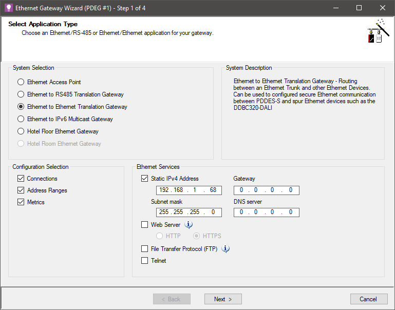
Under System Selection, select Ethernet to Ethernet Translation Gateway.
-
Select Static IPv4 Address and enter the EG’s IP Address (as well as Gateway and Subnet mask if required).
-
Under Configuration Selection, ensure Connections is selected and click .
-
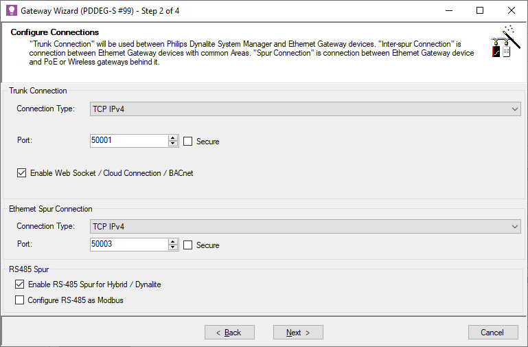
Set the Trunk Connection > Connection Type to TCP IPv4 on Port 50001.
Set the Ethernet Spur Connection > Connection Type to TCP IPv4 on Port 50003.
Confirm required checkbox selection and click to continue.-
 Secure (both) should be unticked. For secure gateway setup, refer to PDDEG-S Site CA Certificate and Secure Ethernet to Ethernet below.
 -
 Enable WebSocket / Cloud Connection / BACnet enables WebSocket trunk connectivity for SB/SM, cloud connectivity for Dynalite Cloud, and BACnet for BMS integration.
 -
 Enable RS-485 Spur for Hybrid / Dynalite configures routing if the gateway is connected to a DyNet RS-485 spur.
 -
 Configure RS-485 as Modbus converts the RS-485 port from DyNet to Modbus for use with Modbus Power Meters
-
-
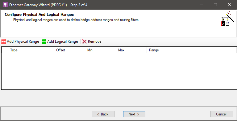
Click (Do not add any physical or logical ranges).
Ensure Device Online Status is
 Enabled and click .
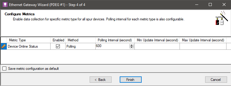
The wizard adds three new routing records:
-
IPv4 TCP Port 50001 → IPv4 TCP Port 50003
-
IPv4 TCP Port 50003 → IPv4 TCP Port 50001
-
IPv4 TCP Port 50003 → IPv4 TCP Port 50003
The last routing record is only required when multiple DDBC320-DALI controllers share common areas. When the network is busy, there may be performance issues as this routing record will result in all messages from every DDBC320-DALI being routed to all other DDBC320-DALI controllers. In this case it may be necessary to have separate secure ports (with different port numbers) for groups of DDBC320-DALI controllers with common areas.
Additional routing records may be added according to the options (if any) selected on the Configure Connections step.
PDDEG-S Site CA Certificate
Firstly, you must create/import a Site CA Certificate in System Builder.
Creating secure Ethernet connections requires a PDDEG-S. To ensure end-to-end security, each PDDEG-S and Ethernet device must be configured for secure connections in the job before importing the job into SM.
To enable SM to connect securely to the PDDEG-S gateways in the system, Open SB on the SM Server machine and import the Site CA certificate to that machine and save the job/database.
SB enables you to:
-
Connect to the system via a secure trunk connection.
-
Manage site certificates.
-
Upload Device Site Certificates to devices.
-
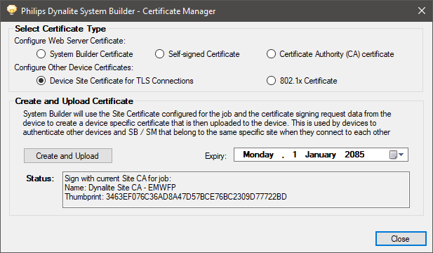
Right-click the PDDEG-S in System view and select Gateway Actions >
 Manage Certificate…
 -
Click Select Certificate Type > Device Site Certificate for TLS Connections.
-
Click the button. After 1-2 minutes, System Builder creates and uploads a signed certificate file to the gateway.
-
Click the button.
Secure Ethernet to RS-485
-
Right-click the EG in System view and select
 Bridge Configuration Wizard… or press Alt+W.
 -
Select Ethernet to RS-485 Translation Gateway.
-
Enter an IPv4 address
Ensure that  Web Server is NOT selected.
-
Click the button.

-
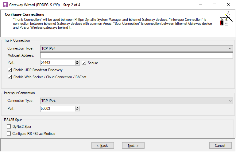
Set the Trunk Connection > Connection Type to TCPv4 on Port 51443 and tick the
 Secure checkbox.
Set the Inter-spur Connection > Connection Type to TCPv4 on Port 50003.-
 Enable UDP Broadcast Discovery enables the UDP IPv4 discovery port (Port 9998) used by SB to find the bridges in the system (listed in the Connection Settings page under Ethernet Trunk Connection Settings). It also enables DynamicTouch access.
 -
 Enable WebSocket / Cloud Connection / BACnet enables WebSocket trunk connectivity for SB/SM, cloud connectivity for Dynalite Cloud, and BACnet for BMS integration.
 -
 DyNet2 Spur routes DyNet2 messages from the trunk onto a DyNet2 RS-485 spur.
 -
 Configure RS-485 as Modbus converts the RS-485 port from DyNet to Modbus for use with Modbus Power Meters
Click the button.
-
-
Click and enter Offset, Min and Max values.
-
Click and enter Offset, Min and Max values. Primary address Min value must be 1 or 0 (see note below).
-
OPTIONAL: Click again to enter address ranges that are common to multiple EGs. The range defined by the Min and Max values must not overlap with the other logical ranges.
SB lists the EG devices that it finds in the job that share common address ranges. The address ranges must match exactly.
-
Click the button.
Do not use common areas unless you have a genuine need to control areas on different floors from a user interface/sensor on another floor. When finishing the wizard, it will ask if you want to automatically create the additional routing between the gateways with common areas. 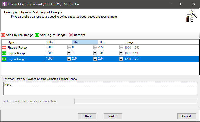
-
Either leave the default metrics on the spur, or enable/disable/modify them as required.
-
Click the button, then click the to close the confirmation message.

-
Record the box number and IP address of each gateway in your project notes for future reference.
-
Press F12 or click
 Save to Device.
 -
Click File >
 Save to save the job to your PC.
Secure Ethernet to Ethernet
Configuring the PDDEG-S as a secure Ethernet to Ethernet Translation Gateway uses the site’s LAN to securely connect one or more Dynalite Ethernet devices, such as the PDZG-E Zigbee gateway, or the DDBC320-DALI controller (via its Ethernet port), to the Dynalite system.
When configured, SB and SM connect to the PDDEG-S gateways via TLS TCP connections. The PDDEG-S gateways then connect to each Ethernet device via separate TLS TCP connections.
A maximum of 25 Ethernet devices can be connected to each PDDEG-S. Up to three DDBC320-DALI controllers can be configured with the same offset to behave as a single spur.
|
-
Right-click the EG in System view and select
 Bridge Configuration Wizard… (Alt+W).
 -
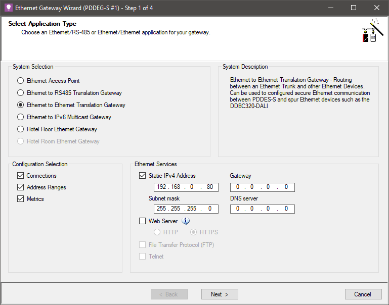
Under System Selection, select Ethernet to Ethernet Translation Gateway.
-
Select Static IPv4 Address and enter the EG’s IP Address (as well as Gateway and Subnet mask if required).
-
Under Configuration Selection, ensure Connections is selected and click .
-
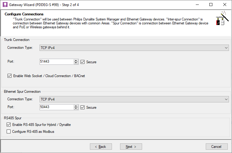
Set Trunk Connection > Connection Type to TCP IPv4 on Port 51443, and tick the
 Secure checkbox.
Set Ethernet Spur Connection > Connection Type to TCP IPv4 on Port 50443, and tick the Secure checkbox.
-
 Enable WebSocket / Cloud Connection / BACnet enables WebSocket trunk connectivity for SB/SM, cloud connectivity for Dynalite Cloud, and BACnet for BMS integration.
 -
 Enable RS-485 Spur for Hybrid / Dynalite configures routing if the gateway is connected to a DyNet RS-485 spur.
 -
 Configure RS-485 as Modbus converts the RS-485 port from DyNet to Modbus for use with Modbus Power Meters
Click .
-
-
Click (Do not add any physical or logical ranges).

-
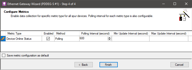
Ensure that Device Online Status is Enabled and click .
The wizard adds three new routing records:
-
IPv4 TCP Port 51443 → IPv4 TCP Port 50443
-
IPv4 TCP Port 50443 → IPv4 TCP Port 51443
-
IPv4 TCP Port 50443 → IPv4 TCP Port 50443
This last routine record is required only when different DDBC320-DALI have common areas. When the network is busy, there may be performance issues as this routing record will result in all messages from every DDBC320-DALI being routed to all other DDBC320-DALI controllers. In this case it may be necessary to have separate secure ports (with different port numbers) for groups of DDBC320-DALI controllers that have common areas.
Additional routing records may be added according to the options (if any) selected on the Configure Connections step.
Connecting to the Ethernet Trunk
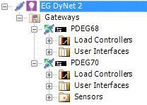
Once each EG has been configured as a DyNet translation bridge, it will carry DyNet2 messages over the Ethernet trunk. The bridge translates the DyNet1 messages on the spur to DyNet2 on the trunk.
When SB is connected to the trunk, all configured EGs are automatically connected and are marked with the ![]() 'connected upstream' icon.
'connected upstream' icon.
In a multi-spur network, SB can communicate using an Ethernet trunk connection. This allows one commissioning engineer to commission the entire system from a single PC.
|
-
Plug your PC into the router router/switch with an Ethernet cable, or connect over Wi-Fi.
-
Ping the IP address of each EG to check the connection (ensure your PC is on the same subnet as the EGs).
-
Launch SB. If you haven’t already added the EGs to the current job, add them now by searching or sign-on.
-
Select the job name in the Device tree.
-
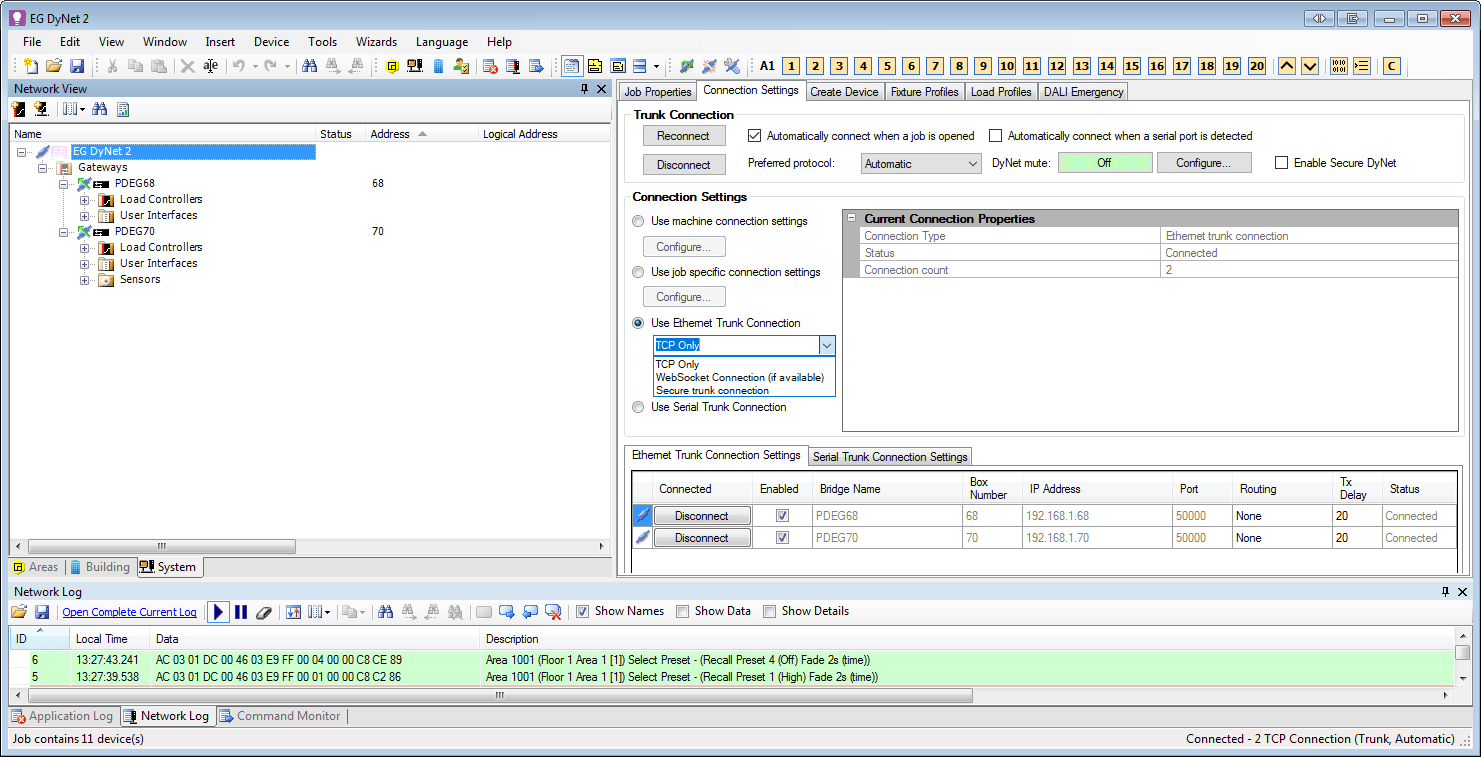
Open the Connection Settings tab and select Connection Settings > Use Ethernet Trunk Connection.
-
From the dropdown list, select the required connection type:
-
TCP only
-
WebSocket Connection (if available)
-
TCP TLS (Secure Trunk)
The EGs in your system are listed in the Ethernet Trunk Connection Settings table at the bottom of the page, with each EG’s Bridge Name, Box Number, IP address, Port, Routing, Tx Delay and current Status.
From here, all connections can be enabled/disabled (see screenshot below).
-
-
At the top of the page, under Trunk Connection, click the button.
SB connects to each EG using the connection settings previously defined by the Bridge Configuration Wizard.
|
Connecting to a Serial Spur
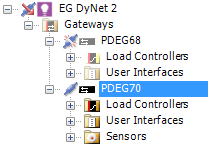
In an RS-485 multi-spur network, SB can communicate with the network using a spur connection to a trunk gateway (EG or DDNG485). This allows multiple people to configure different parts of the system at the same time, considerably reducing commissioning time.
-
Plug a USB PC node into the commissioning PC and then into a DyNet port on the same spur as the EG.
-
Launch SB.
-
In the Device tree, select the EG you want to connect to.
-
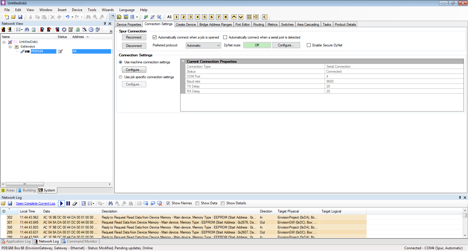
Open the Connection Settings tab and select either Use machine connection settings or Use job specific connection settings.
-
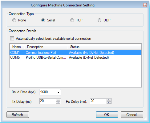
Click the button. SB displays a list of discovered connections.
-
Select Connection Type > Serial and in the Connection Details list select Prolific USB-to-Serial, then click the button.
-
At the top of the page, click the Spur Connection > button. SB connects to the selected EG.
-
Confirm that you are connected to the correct EG in the Device tree before adding other devices to the spur.
|