DyNet Messaging
Addressing
Port 1 uses the DyNet protocol to communicate with the Dynalite system, using two addressing methods:
Physical Addressing
Physical addressing is mainly used during the testing and commissioning stage to configure DyNet devices. It is also used for physical, location-specific parameters such as circuit breaker trip signaling.
To identify a lighting circuit with physical addressing, you need the:
-
Device type
-
Box number
-
Physical channel (circuit/driver) number
Logical Addressing
Logical addressing is used in the lighting system’s day-to-day operation. Lighting circuits and controls are configured to logical areas, independent of the physical device they are connected to. A single DyNet network spur supports up to 255 separate areas, each containing up to 255 channels. Multiple spurs can be linked together, enabling massive network scalability.
To identify a lighting circuit/driver with logical addressing, you need the:
-
Area number
-
Channel number
Area numbers are used to group related lighting fixtures by the area/room they are in.
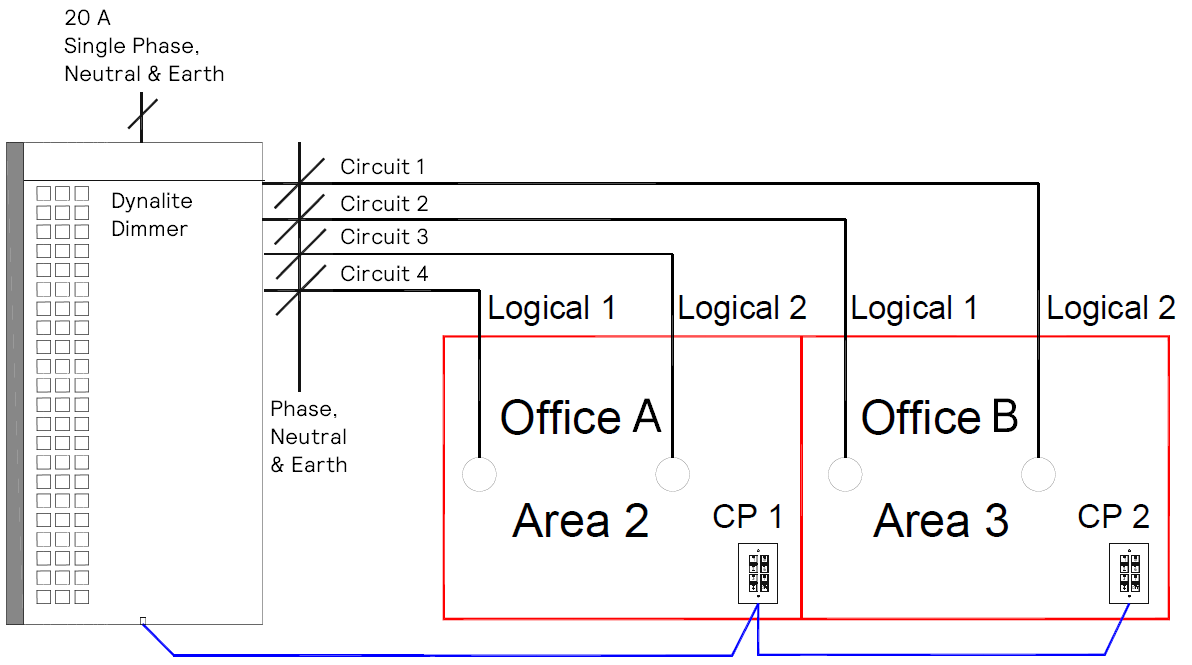
A single load controller supplies power to lighting circuits in two offices, each with its own control panel. The lighting circuits and control panel in Office A are assigned to Area 2, while those in Office B are assigned to Area 3.
This is all the configuration required to ensure that the Office A panel only controls the Office A lighting circuits, and the Office B panel only controls the Office B lighting circuits. The two rooms operate independently of one another, despite being connected to the same controller.
Join and Message Filtering
The Join feature is primarily used to provide a room linking system. This feature is used in ballrooms, function rooms, training rooms, etc. that contain movable partition walls, to automatically provide full or separate room control from the control panels depending on whether partition walls are open or closed.
The commissioning engineer programs the join levels for an area, and can provide the area join level details to a complementary system programmer as needed.
In a standard message, all Join bits are on. Therefore, the default Join byte is set to 0xff. A join byte of 0x00 will cause a message to have no effect on the state of the network. It is therefore possible to filter messages to channels within an area using different values for the Join byte. Channels can be configured to only respond to messages if a specific bit is set in the Join byte. This feature enables the system to precisely target messages to multiple devices/channels by a setting the Join byte of a transmitted message.
| If a third-party system is controlling an area that is part of a Dynalite join system, the commissioning engineer on the project should use the Set RMask message in addition to a Join message when changing the Join state. This allows third-party devices to use native join preset messages to control more than one area. Refer to the Join and Area Linking Commissioning Guide for more information. |
LED Tracking
The button LEDs on wall-mounted control panels are used to indicate an area’s current preset scene. When a preset message is transmitted on the network, any button on any panel that also recalls that preset for that area will illuminate. Any button that recalls a different preset for that area will turn off. Thus all affected panels provide an accurate representation of the area’s current state.
Connecting SB to the DDNG232
-
Plug the commissioning PC into a USB PC Node and then with an RJ12 or RJ45 connector, connect the PC node to a dingus and plug the dingus into the DyNet port on the gateway.
-
Select Use machine connection settings or Use job specific connection settings.
-
Connect SB to the RS-485 network using a serial connection.
(Alternatively, you can connect over TCP/IP to an Ethernet gateway with an RS-485 connection to the DDNG232).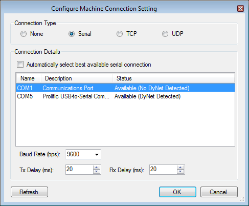
The Baud rate must be set at same speed as configured in the DDNG232 Port 1 where SB is connecting (default: 9600 baud). -
Add the device to your project using one of the following two methods:
-
 Insert Device from List - to pre-commission the device.
 -
 Insert Devices from Network - to search for the device (Device Code: 0xC4) or sign on the device.
-
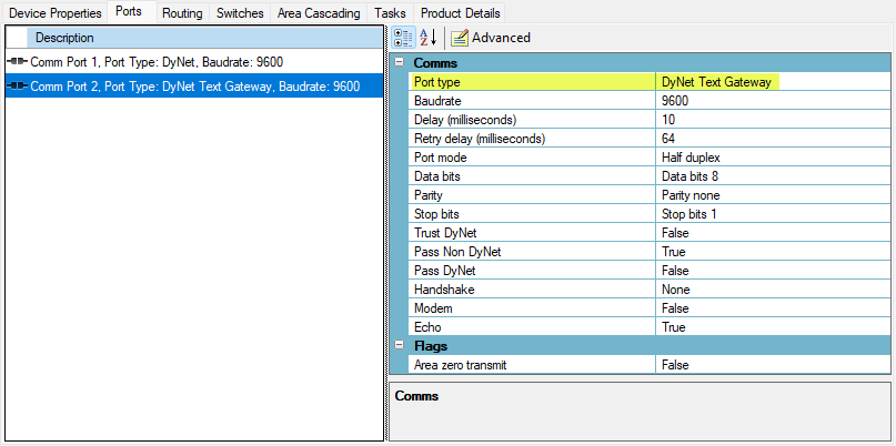
Configuring the RS-232 Port
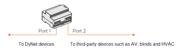
The DDNG232 has two ports:
-
Port 1 is the RS-485 DyNet port for communicating with the Dynalite system (no configuration required).
-
Port 2 is the RS-232 port for sending/receiving RS-232 or DyNet Text packets.
-
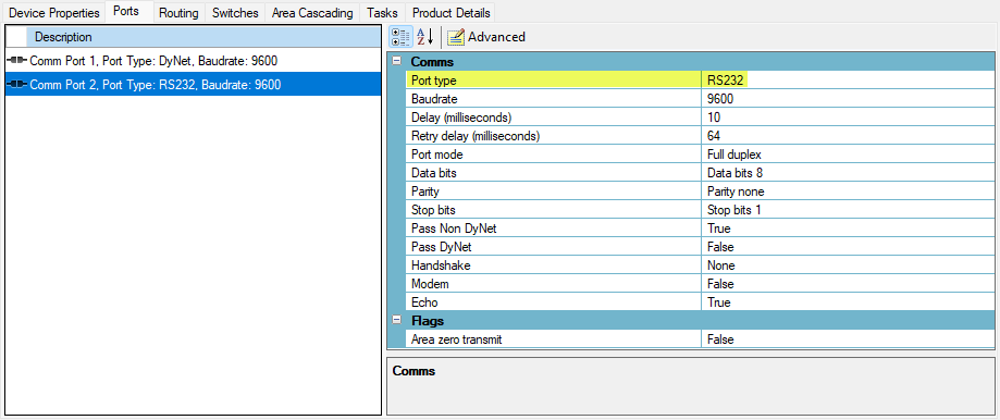
In System view, select the device and click the Ports tab.
-
Select Comm Port 2.
-
In the Port type dropdown list, select one of the following:
-
RS-232 to send and receive DyNet packets to control/monitor a third-party device from a task in the gateway.
-
DyNet Text Gateway to send and receive ASCII strings to control the Dynalite system.
-
-
Click
 Save to Device (F12).