View Window
The View Window lets you select a logical, network, or physical item in your system. When an item is selected, you can access common functions from the toolbar or by right-clicking the item name in the tree to open the context menu. There are three views:
Areas View
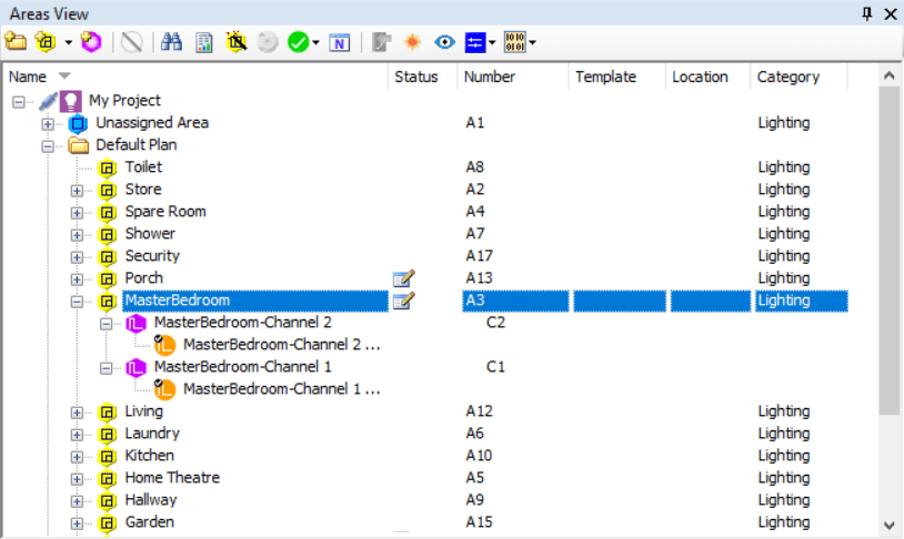
Areas View displays all the logical components in the job. It allows areas to be grouped together into folders and channels to be linked to circuits. All logical items can be given meaningful names and descriptions. The Areas View tree displays the following items:
-
 Folders
 -
 Areas
Areas -
 Channels
 -
 Circuits (or lamp drivers)
Areas View displays the following information columns by default:
-
Area/Channel number
-
Location
You can customize your column selection, width, and order by clicking on the column headings.
To exclude an area from user interface apps that read the project.xml file in the Ethernet Gateway, open the Properties Window > Area Properties tab and set Category Options > Category to Hidden.
|
The following icons indicate different channel/output types:
| Channel Type | Output Type | ||
|---|---|---|---|
|
Leading Edge |
|
Leading Edge |
|
Trailing Edge |
|
Trailing Edge |
|
Relay |
|
Relay |
|
0-10 Volts |
|
0-10 Volts |
|
DSI |
|
DSI |
|
LED |
|
LED |
|
Volt Free |
|
Volt Free |
|
Fan |
|
Fan |
|
DALI |
|
DALI |
|
Leading Edge 4 Amp |
|
Leading Edge 4 Amp |
|
Curtain |
|
Curtain |
|
DMX Tx |
|
Leading Edge 5 Amp |
|
Red Preset Color |
|
Trailing Edge 5 Amp |
|
Green Preset Color |
|
DMX |
|
Blue Preset Color |
|
Unassigned |
|
Warm White |
|
Emergency |
|
Cool White |
|
Unknown (DALI short address) |
|
Tuneable White |
|
Error (DALI short address) |
|
Not Set |
||

System View
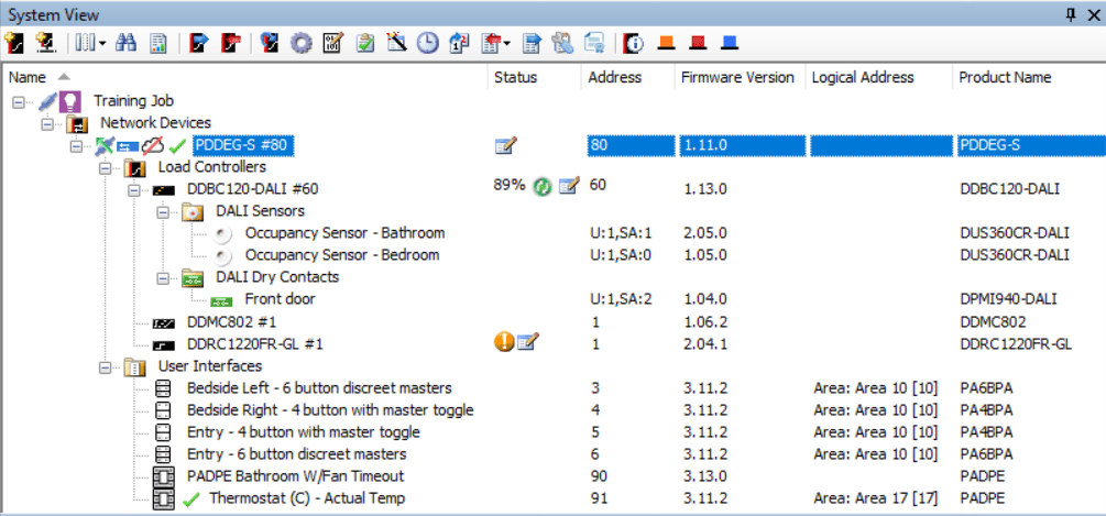
System View shows the network topology (trunks, spurs, and devices) and the SB connection point, with devices grouped by product category:
-
 Load controllers
 -
 User interfaces
 -
 Sensors
 -
 Dry contacts
 -
 Network Devices
 -
 Meters
 -
 Other devices
System View displays the following default information columns:
-
Status
-
Address (Box Number)
-
IP Address
-
Logical Address
-
Product Name
-
Sequence
-
Device Location
-
Product Category
-
Product Type
-
Serial Number
-
Device Code
-
Firmware Version
| Each device’s default box number is based on the last two digits (00-99) of its serial number. Different device types can have the same box number without causing a conflict, but two devices of the same type must have different box numbers to operate on the same network. |
Icons next to each device in the tree indicate that device’s current status. These device status icons also appear in Building View.
-
 Device modified in SB but data not yet saved to device.
 -
 Device Communicating
 -
 Device has Tasks/Events
 -
 Device has an unassigned address
 -
 Device Offline
 -
 Device Warning
-
Device Unsynchronized (SB detected that device configuration has been modified since last read/write. Solution is to either reload device data or select to resave all device data)
-
-
 Device Error
-
Box Number Conflict
-
Boot Loader Running (firmware not running, probably caused by firmware upgrade incomplete)
-
Logical Translation Error (logical configuration value outside valid range for bridge translation)
-
Physical Translation Error (physical configuration outside valid range for bridge translations)
-
| Each device’s status is visible in a mouseover tooltip, and in the status bar at the bottom of the main application window when the device is selected. |

Building View
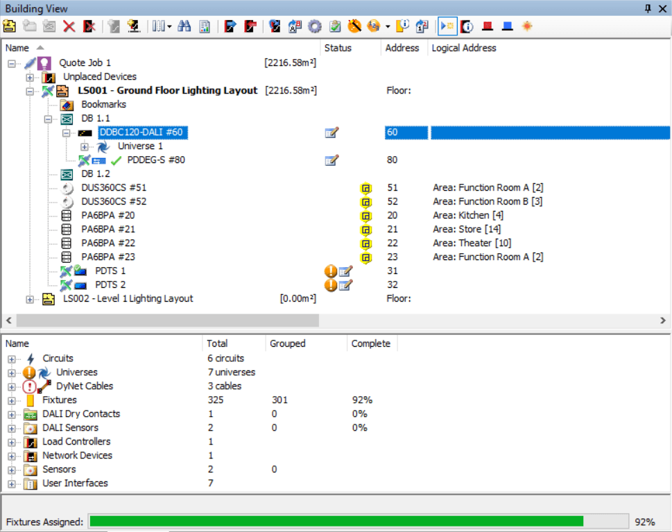
Building View represents the physical location of devices and channels in the job. It allows different floor plans and layouts to be added and provides bookmarks to remember locations on the floor plan. Building View displays devices grouped according to their location.
The Building View tree displays the following items:
-
 Unplaced devices
 -
 Floor plans
 -
 Folders
 -
 Distribution boards
 -
 Bookmark folders
 -
 Bookmarks
 -
 Devices
 -
 Outputs (circuits/lamp drivers)
You can link items in the different views by dragging them to the other view tabs.

The Building View tree displays the following information columns:
-
Device Address (Box Number)
-
IP Address
-
Logical Address
-
Device Status
-
Product Name
-
Sequence
-
Device Location
-
Product Category
-
Product Type
-
Serial Number
-
Device Code
-
Firmware Version
The following icons indicate each outputs’s status:
-
 Linked to a fixture
 -
 Assigned to an area
Building View represents the items placed on the floor plan. A project can contain more than one floor plan. You can place devices directly on a floor plan, or within distribution boards on the plan. Otherwise they are listed in the Unplaced Devices folder.
| Using a floor plan is optional as all devices created in Building view also appear in System view. A system can be fully commissioned without using Building View. |
