PDTS Commissioning
-
Connect the PDTS to the same Ethernet LAN (and/or DyNet RS-485 network) as SB and power it on (see PDTS Installation Instructions).
-
Add the PDTS to the SB job.
-
Connect SB to the PDTS.
-
Set the Device Properties.
-
Configure the real-time clock.
-
Add a User (required for uploading files).
-
Create and configure any required Schedules.
-
Upload project.xml and/or PDTS UI Creator) /custom web page files.
-
Configure Ethernet gateway functions.
| SB can also communicate with the PDTS via RS-485 DyNet using the PD-PCN USB adaptor, but this connection is too slow for firmware updates and UI/file uploads. |
| The PDTS is factory-configured to accept secure IPv4 connections on port 51443 using the default SB factory certificate. For optimal security, we recommend adding your own Site CA certificate before final deployment. |
Add the PDTS to System Builder
Unless pre-commissioning, the PDTS must be powered on and connected to the same Ethernet LAN as SB.
Add the device to your project using one of the following methods:
-
To pre-commission the device, click
 Insert Device from List.
 -
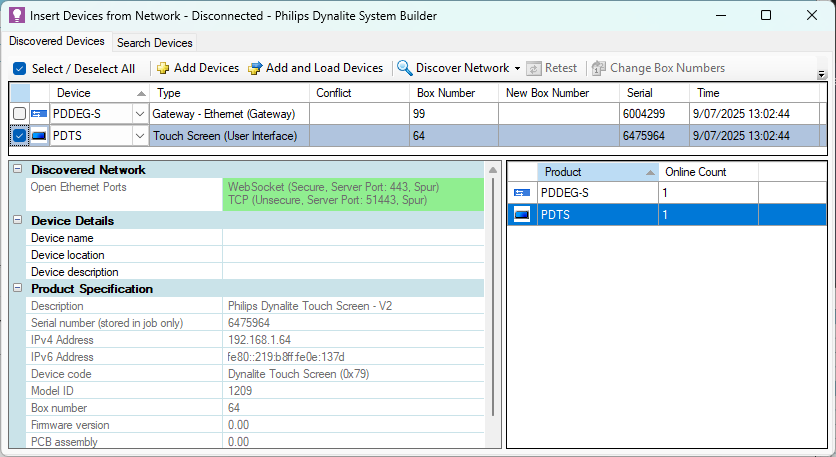
If SB and the PDTS share a LAN connection, click
 Insert Devices from Network, then click
  Discover Network > Discover Devices over Ethernet
 -
If SB and the PDTS only share a DyNet connection, click
Insert Devices from Network to search for the device (Device Code 0x79), or sign on the device using the service switch.
Connect SB to the PDTS (Ethernet Trunk)
|
The default IP address for the PDTS is 192.168.1.\[box number]. The box number is shown in the Device Properties tab, the System View > Address column, and in the last two digits under the QR code on the device serial label. You can change the device’s IP address in the Ports editor. If so, we suggest also updating the box number in Device Properties to match. If your LAN uses DHCP, we strongly recommend reserving the device’s IP address to avoid network conflicts. |
-
In the SB job Connection Settings tab, select either Use machine connection settings or Use job specific connection settings and click the button to open the Configure Connection Setting dialog
-
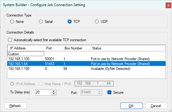
Select TCP and wait for the available connections to load.
-
If the PDTS IP address loads, select it. Otherwise, manually enter the IPv4 address, Port 51443, and tick the Secure checkbox. Click .
-
Once connected, select the PDTS in System View and click
 Load From Device ( F11 ).
| If connecting to the PDTS via another Ethernet gateway (e.g. PDDEG-S), |
Configuration Steps
Device Properties
Enter the relevant Device Properties for your application.
Real-Time Clock
The PDTS’s internal astronomical clock enables advanced scheduling of system actions and automated tasks based on time of day or sunrise/sunset. Setting the time zone and local time will ensure that schedules and event logging function correctly.
-
The time zone is set for the whole job and must be saved to the device. When pre-commissioning devices, ensure that you select the correct local time zone for the project site.
-
Local time is set for each clock in the system and is synchronised immediately without having to save to the device. The local time must be reconfigured if the device is factory-reset.
-
In the toolbar, click Tools >
 Set Location and Time Zone.
 -
Select the Country and City from the dropdown lists.
-
Click the button.
-
Click
 Save To Device (F12).
-
In System View, right-click the device and select
 Set Realtime Clock….
 -
Under Set Device Time, select one of the following:
-
Synchronise with PC Time to set the real-time clock to your PC time.
-
Manually Set Device Time to specify the time and date.
-
-
Click the button to save your changes.
-
Click the button to exit the dialog.
| The PDTS can be configured to broadcast date and time messages to other devices - See Device Properties > Real-Time Clock. |
Add User
A user account is required in order to upload firmware updates, project.xml files, PDTS UI Creator) projects, and/or custom web pages.
| This user account is separate from the default/custom user accounts created on the PDTS. |
-
Select the PDTS and open the Users tab.
-
Click
 Add to create a new user. You can add a maximum of five users, but only one is required.
 -
Enter the Name and Password (maximum 40 characters, case-sensitive).
-
Re-enter the password in the Confirm Password field.
-
Set Enable to True.
-
Either leave the General Permissions, Web Server Permissions, and Feature Permissions Enabled (default), or change to Disabled if required.
-
Open the Device Properties tab and set Ethernet Applications > Authentication required for to None (default) or CGI only as required.
-
Click
Save To Device (F12).
If usernames or passwords are forgotten and you don’t have the original job file, they can be retrieved by connecting SB to the PDTS and clicking ![]() Load from Device ( F11 ). Passwords are not readable, but can be manually updated.
Load from Device ( F11 ). Passwords are not readable, but can be manually updated.
Schedules
You can create and manage schedules on the PDTS in the Schedules tab and/or on the PDTS itself. There are 40 undefined placeholder schedules included by default that you can configure for any purpose.
Uploading Files
Project.xml
Once you have completed the project’s logical configuration (areas, channels, and preset names), you can upload your project.xml file to the device for use with the default UI.
In System View, right-click the device and select Gateway Actions > ![]() Upload Configuration > Upload Logical Configuration.
Upload Configuration > Upload Logical Configuration.
| To save a copy of your project.xml file to your PC, click File > Export > Logical Data… and then click the button on the export dialog. |
PDTS UI Creator Projects
See UI Creator to build and upload your own UI project.
Custom Web Pages
To upload a custom web interface, right-click the device, select ![]() Upload Custom Web Pages… and follow the prompts.
Upload Custom Web Pages… and follow the prompts.
Refer to the CGI Commands reference for available functions.
|
![]() Reset the device to apply the new files/configuration.
Reset the device to apply the new files/configuration.
Click ![]() Save To Device ( F12 ) after making any configuration changes. The PDTS will reset after saving.
Save To Device ( F12 ) after making any configuration changes. The PDTS will reset after saving.
Ethernet Gateway
The PDTS can act as a secure Ethernet gateway to the rest of the Dynalite system, replicating many of the functions of the PDDEG-S, and can be easily configured using the ![]() Bridge Configuration Wizard.
Bridge Configuration Wizard.
Please refer to the following sections of the Ethernet Gateways > Commissioning guide: