Ports
The EG supports serial and Ethernet ports. The Ports editor configures the serial port and the IPv4/IPv6 addresses and ports for connection to the system and to the commissioning PC.
The Port type can be set to DyNet1, DyNet2, Fidelio, or Text and Binary Integration to define the trunk-and-spur topology of the system, or to connect to a third-party device/system.
|
To ensure correct routing, we recommend adding ports via the |
Properties
|
Standard properties are shown in bold. Advanced properties are shown in italics. Displayed fields can be sorted in one of two ways by clicking the following icons: Initially only the basic fields are shown. To reveal all fields, click the |
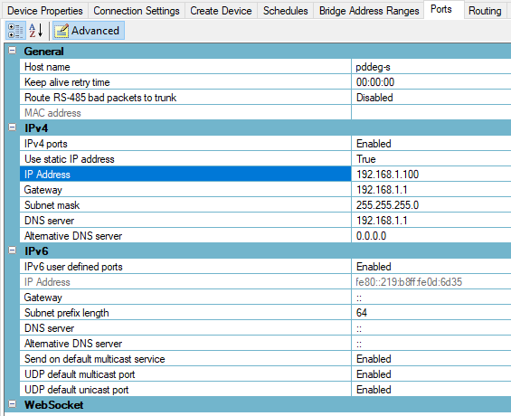
General
| Property | Description |
|---|---|
Host Name |
Name displayed on the router’s connected devices page. |
Keep alive retry time |
The time between sending TCP keep-alive messages if no other message has been sent or received. |
Route RS-485 bad packets to trunk |
If enabled, bad packets received on the RS-485 spur are routed to the trunk port inside a valid DyNet2 message. These can then be viewed in the Network Log to help diagnose network issues. |
MAC Address |
A hardware identification number that uniquely identifies each device on a network. |
IPv4
| Property | Description |
|---|---|
IPv4 ports |
Enabled/Disabled |
Use static IP address |
True/False |
IP address |
The IP address of this device |
Gateway |
LAN’s NAT gateway IPv4 address |
Subnet Mask |
A 32-bit number that divides an IPv4 address into network address and host address. A subnet mask is made by setting network bits to all ones and setting host bits to all zeroes. |
DNS server |
Domain Name Server address |
Alternative DNS server |
Alternative Domain Name Server address |
IPv6
| Property | Description |
|---|---|
IPv6 user defined ports |
Enabled/Disabled |
IP Address |
IPv6 address |
Gateway |
LAN’s NAT gateway IPv6 address |
Subnet prefix length |
The IPv6 prefix length is equivalent to an IPv4 subnet mask. Default: 64. |
DNS server |
Domain Name Server address |
Alternative DNS server |
Alternative Domain Name Server address |
Send on default multicast service |
Enabled/Disabled (disable for system security purposes) |
UDP default multicast port |
Enabled/Disabled (disable for system security purposes) |
UDP default unicast port |
Enabled/Disabled (disable for system security purposes) |
Adding Ports
Click ![]() Add to add an
Add to add an ![]() IPv4 port or
IPv4 port or ![]() IPv6 port to the device.
IPv6 port to the device.
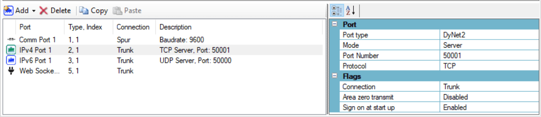
Port
| Property | Description |
|---|---|
Port type |
DyNet1, DyNet2, Fidelio, or Text & Binary Integration.
Each port’s Index is its sequence number within the group. |
Mode |
Defines if the controller is acting as the Client or Server. |
IP Address |
The IPv4 or IPv6 address of the remote port |
Port Number |
Port number |
Protocol |
TCP or UDP |
Flags
| Property | Description |
|---|---|
Secure port |
If True, TCP port is secured with TLS encryption. |
Connection |
Specifies a Trunk or a Spur connection for address translation purposes. |
Area Zero Transmit |
Enable all areas messages for diagnostic use. Leave this option Disabled unless advised by Philips Dynalite. |
Sign on at start up |
Enabled/Disabled - sends a sign on message at startup. |
Reply using a unicast message |
True/False. If True, then when a message is received on a UDP broadcast or multicast port, the device will respond directly using a unicast message and not broadcast the response. |
| Comm Port properties are not shown here. Please leave these at default settings. |
VPN/VLAN Notes
Please note the following if deploying a Dynalite system with a System Manager server on a network requiring VPN or VLAN access (e.g. multisite deployments):
The SM server connects over TCP to each individual Ethernet gateway, which must be configured to use a static (or reserved DHCP) IP address.
The following ports are used between SM and EG:
-
50000 (TCP) - This is typically the DyNet trunk connection with each spur. (note: it is not hardcoded but we strongly recommend to use to the defaults)
-
21 (FTP) - When enabled, this port is used to upload the logical configuration to the EG, which populates the EG web interface with area, preset, and channel names.
When common areas are used (logical areas that cross multiple spurs on a location, such as staircases, facade, outdoor areas, etc.), the EGs communicate directly with each other via the following default port:
-
50001 (TCP) - This is the default port used for spur to spur communication between EGs.
| These are the default ports used by the wizard. We strongly recommend keeping these settings, but they can be changed if required. |
If the SM client requires routing to the SM server from a different VLAN, the following ports must be enabled (via WCF architecture):
-
8084 (TCP)
-
8085 (HTTP)
For distributed organisations that use separate VLANs for each location, we recommend adding the Ethernet port of the switch connected to the SM server to all VLAN remote locations. In this case, no routing is required for SM to communicate with the different spurs.
If this is not desired, then it is the IT administrator’s responsibility to configure and maintain any required routing and port forwarding.