Configure Inputs
The Inputs editor contains the following settings to configure analog or switch inputs:
-
General (Advanced)
-
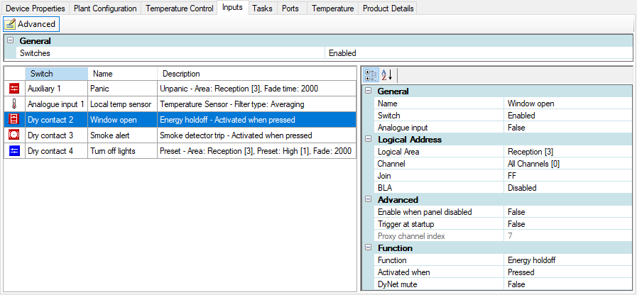
Input Switches list showing function icon, Switch type & number, and Description with the name and function details.
Select a switch to view and configure the following properties:
-
General
-
Logical Address
-
Advanced
-
Analog input or Function
|
Initially only the basic fields are shown. Most standard setups do not require advanced properties, but you can reveal all fields by clicking the button. Displayed fields can be sorted in one of two ways by clicking the following icons: Refer to the property description pane at the bottom of the editor for explanations of each property. |

| The local temperature sensor must be configured on Input 1. |
-
Select an input switch.
-
Input 1 only: Set Analog input to True for a local temperature sensor, or False for a dry contact input.
-
Select and configure the applicable properties for each input as required (see below).
-
Press F12 or click
 Save to Device.
| Standard properties are shown in bold. Advanced properties are shown in bold italics. |
| Property | Description |
|---|---|
General (Advanced) |
|
Switches |
Enabled/Disabled. Affects all switches. |
| Property | Description |
|---|---|
General |
|
Name |
User-specified switch name. |
Switch |
Enabled/Disabled for a single switch. |
Analog input |
Select True for temperature sensor (Input 1 only) or valve position sensor, or False for dry contact input. |
Logical Addresses |
|
Logical Area |
Sets the area where the switch will be used. |
Channel |
Sets the affected channel. Select a channel or use All Channels (0). |
Join |
Assign any join rows that are applicable using the join byte. |
BLA |
Base Link Area Enabled/Disabled. |
Advanced |
|
Enabled when panel disabled |
If True, function is still available in panic mode. |
Trigger at startup |
If True, switch action is force-triggered at startup. Defined action will be executed based on switch state (pressed or released) when device is reset. |
Proxy channel index |
Can be referenced in a custom action using Action Chain Editor > Preset (Advanced) to send a DyNet message to a different logical address. Allows you to specify the proxy channel index of a different input to use the logical address associated with that input. |
Analog input |
|
Type |
Sets the input to Temperature sensor (Input 1 only) or Valve position sensor. |
Sample Period (milliseconds) |
Period between samplings. |
Filter type |
Set to All pass (no filter) or Averaging (uses the Averaging filter parameter to remove noise and smooth the temperature values). |
Averaging filter parameter |
Default: 64 |
Function |
|
Function |
Select one of the following functions to display the specific function properties:
|
Activated when |
Pressed/Released |
DyNet mute |
If True, stops DyNet messages being created by this function. |
Preset |
Selected preset |
Fade (rounded to 10 ms) |
Default: 00:00:02:000 (hh:mm:ss:mmm) |
Custom Functions |
|
Press actions Release Actions Extended press actions Extended release Actions |
Click the button to select the action(s) from the Action Chain Editor:
|