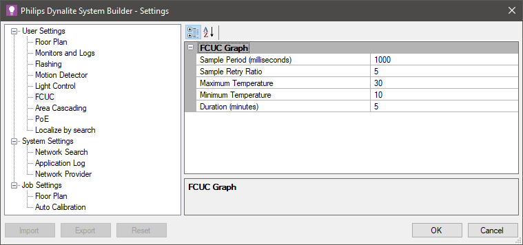
Configure Temperature Control
The Temperature Control editor contains settings for temperature control using a PID or Staged control scheme and ![]() FCUC Diagnostics.
FCUC Diagnostics.
Modes
In both PID and Staged control schemes, you can click the ![]() Add,
Add, ![]() Remove,
Remove, ![]() Copy, or
Copy, or ![]() Paste icons to create up to ten Modes as required. Each PID and Staged control mode has its own Properties page.
Paste icons to create up to ten Modes as required. Each PID and Staged control mode has its own Properties page.
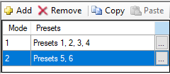
Each mode must be assigned to one (default) or more presets, and is launched whenever the FCUC detects the configured preset(s). Each preset can only trigger one mode.
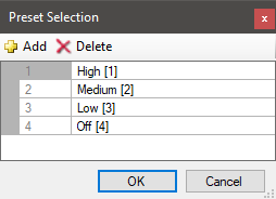
Click the button on the right side of the Mode row to open the Preset Selection box and ![]() Add or
Add or ![]() Delete presets.
Delete presets.
The example modes below illustrate a typical setup focusing on energy savings:
-
Occupied mode - Small setpoint offset ensures that temperature tracks closely to the setpoint for occupant comfort.
-
Unoccupied mode - Larger setpoint offset allows more lenient tracking, reducing energy consumption as HVAC does not need to run continually.
-
Auto mode - Setting Manual fan control to False assigns fan control to the temperature control scheme (PID or Staged).
-
Manual mode - Setting Manual fan control to True allows the fan to be controlled over DyNet by the user.
-
Off Mode - To turn off the FCUC:
-
PID control - Set Dead band fan speed to Off and Cooling/Heating control to Disabled.
-
Staged control - Set Dead band fan speed to Off and set Cooling/Heating stage count to 0 (zero).
-
| If no configuration is defined for a received preset, the preset is ignored and the controller continues to operate in its current mode. |
PID Control Scheme
PID control precisely maintains the temperature based on the PID algorithm to determine the temperature error and control effort required. Each PID control mode must be assigned to one or more preset states.
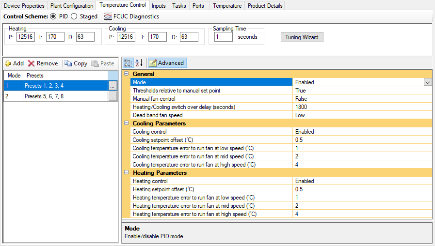
Selecting the PID control scheme displays the following settings:
-
PID parameter values with button
-
Mode list and Preset selector
-
General, Cooling Parameters, and Heating Parameters
| Refer to the property description pane at the bottom of the editor for explanations of each property. |
Tuning Wizard
The PID values are shown in the toolbar when the PID control scheme is selected. We recommend using the to find and set PID parameters.

Heating/Cooling
These fields define the PID gains for heating/cooling operation.
-
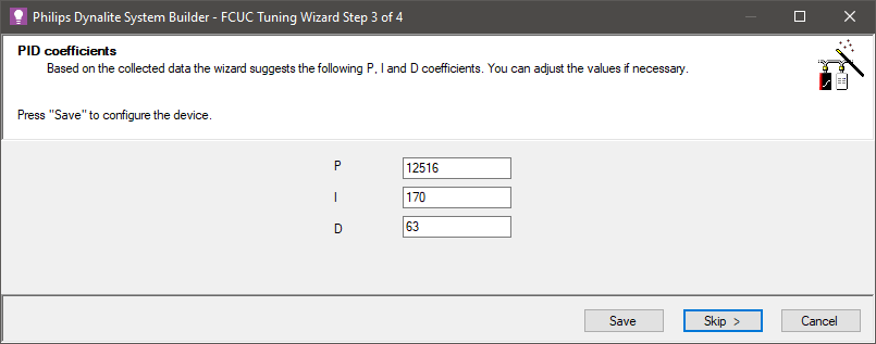
P: The proportional gain for heating/cooling operation of PID in increments of 1
(Range: 0-65534 Default: 12516). -
I: The integral gain for heating/cooling operation of PID in increments of 0.1
(Range: 0-6553.4 Default: 170.0). -
D: The derivative gain for heating/cooling operation of PID in increments of 0.01
(Range: 0-655.34 Default: 63.00).
Sampling Time
This parameter defines the time interval to run the PID algorithm, hence the interval between two calculated control efforts to transfer to the plant (Range: 0.1-25.4 seconds Default: 1.0 second).
Tuning Wizard
-
Click the button.
-
Either:
-
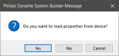
Click the button to load the Temperature Control properties from the device
OR -
Click the button take the configuration from the System Builder job.
-
The tuning of each function should be performed under real operating conditions. For example, tuning for cooling in winter or heating in summer may give inaccurate results.
Tuning the controller involves setting some initial parameters and using these parameters over a period to collect the measured room temperature and observe the controller’s performance.
| Heating and cooling cannot be tuned at the same time. To minimise energy usage, active heating and cooling is not permitted by the controller. |
-
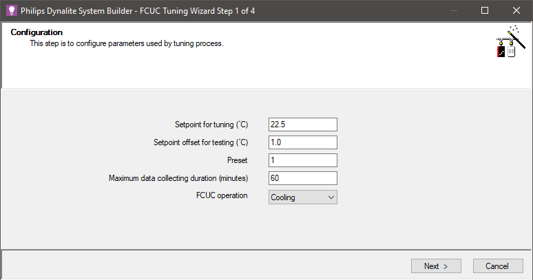
Enter initial parameters:
-
Setpoint for tuning (°C)
Choose a value in the middle of your expected working range. Standard range is approximately 18-24°C in winter and 24°-30°C in summer. This is only used for tuning the controller. It should be reasonably close to your working setpoint. This process does not automatically set the initial setpoint. -
Setpoint offset for testing (°C)
Used to set the positive and negative extremes of the setpoints used for the test relative to the Setpoint for tuning °C. -
Preset
This is the preset used during the tuning test.PID parameters found during tuning are applicable in all operating modes. However, the function selected for tuning (heating or cooling) should match the mode assigned to the preset.
Controller operation is preset-based and the controller must be in a preset state at any given time. This preset is used during tuning
-
Maximum data collecting duration (minutes)
This determines when the wizard will stop collecting data.The Tuning Wizard looks for three full periods of oscillation around the setpoint for a successful test. Normally the test is completed once the test criteria are met. Otherwise, the test will fail when this duration expires.
-
FCUC operation
Select whether to tune the Heating or Cooling function. Only one function can be tuned at a time.
-
-
Click the button to continue.
Click the button to begin the tuning process or the button to go to the next step. You can skip data collection if you already have some approximate values for PID. This saves time if you have already used another tuning tool or commissioned similar areas before.
During tuning, the ![]() Current temperature,
Current temperature, ![]() Setpoint, and
Setpoint, and ![]() Filtered temperature values are plotted on the graph.
Filtered temperature values are plotted on the graph.
Toggle the checkboxes to display the required signals on the chart.
| Filtered temperature averages the temperature values smooth the graph. |
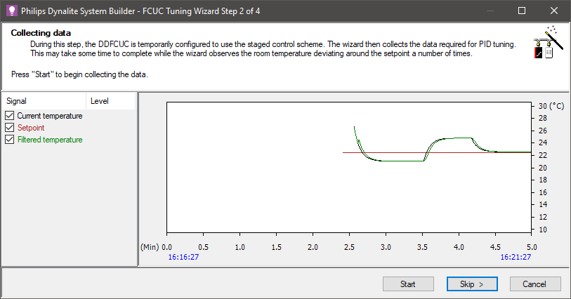
When started, the wizard configures the DDFCUC to use a single staged control scheme with no hysteresis on hot or cold valves and fan set to 100%. The wizard then starts collecting the data required to evaluate PID coefficients, including polling the temperature, setpoint, and controller status.
If the value of the setpoint changes or the function changes between cooling and heating, then the tuning wizard stops and displays an error message.
When enough data is collected, the button changes to . click to proceed to the next step
The wizard now calculates the optimal PID values. Check and adjust these if required.
Click the button to save to the device or click the button to save later. After saving to the controller, the The button changes to . Click to proceed.
Click the button. The controller uses the saved PID values to test its ability to maintain the room temperature.
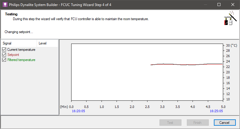
The test succeeds if the standard deviation of the temperature does not exceed the value of the heating or cooling setpoint offset. Assuming normal distribution of the temperature readings, this means that more than 66% of the temperature readings collected are within the configured setpoint offset.
The test can be repeated at any time by pressing the button. The extreme values for the setpoint offset alternate each time the test is run.
Click the button to stop the test and close the wizard.
Staged Control Scheme
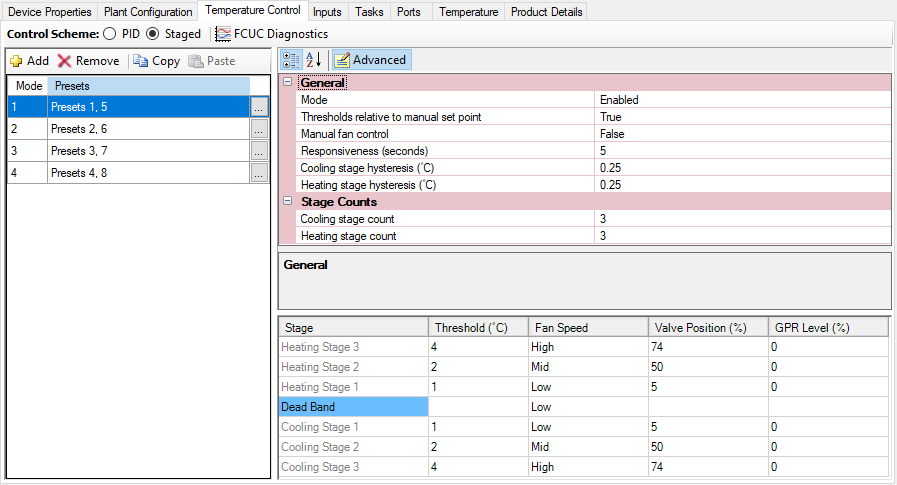
Staged control maintains the temperature based on a stage table to determine the temperature error and control effort required. Each staged control mode must be assigned to one or more presets.
Selecting the Staged control scheme displays the following settings:
-
Mode list and Preset selector
-
General and Stage Counts properties
-
Table showing:
-
Stage
-
Threshold (°C)
-
Fan Speed
-
Valve Position (%)
-
GPR Level (%)
-
The Staged control scheme operates with three heating and three cooling stages and a dead band (Advanced). Each stage is based on the temperature error calculated by the FCU controller during runtime. The Staged control scheme calculates the temperature error at the interval defined by Responsiveness (seconds) and will automatically jump to the appropriate stage to achieve the desired temperature as quickly as possible.
|
If no configuration is defined for a received preset, the preset is ignored, and the controller continues to operate in its current mode. For more information refer to Modes. |
| Refer to the property description pane at the bottom of the editor for explanations of each property. |
Staged control table

The Staged control table configures the control effort required for the relative temperature error from the setpoint.
Enter the parameters required for each heating and cooling stage:
-
Threshold (°C)
This parameter defines relative temperature difference with respect to setpoint temperature for the given control stage. The value increases as stage index increases with respect to dead band (between Heating Stage 1 and Cooling Stage 1). The default values are 1°C, 2°C, and 4°C for three stages in an incremental index. -
Fan Speed
This parameter defines the fan speed (High, Mid, Low, or Off) in each control stage or dead band. The fan speed may be overridden by DyNet if Manual fan control is Enabled. That means any non-zero fan speed received over DyNet as a logical channel level message overrides the value specified in the table. -
Valve Position (%)
This value defines the heating or cooling valve opening position.
100% = fully open, 0% = fully closed. -
GPR Level (%)
This value defines the state of the General Purpose Relay. A non-zero value activates the relay while a zero value deactivates the relay.
FCUC Diagnostics
Click ![]() FCUC Diagnostics to open the FCUC Diagnostics window, which displays a real-time chart of the temperature and plant status.
FCUC Diagnostics to open the FCUC Diagnostics window, which displays a real-time chart of the temperature and plant status.
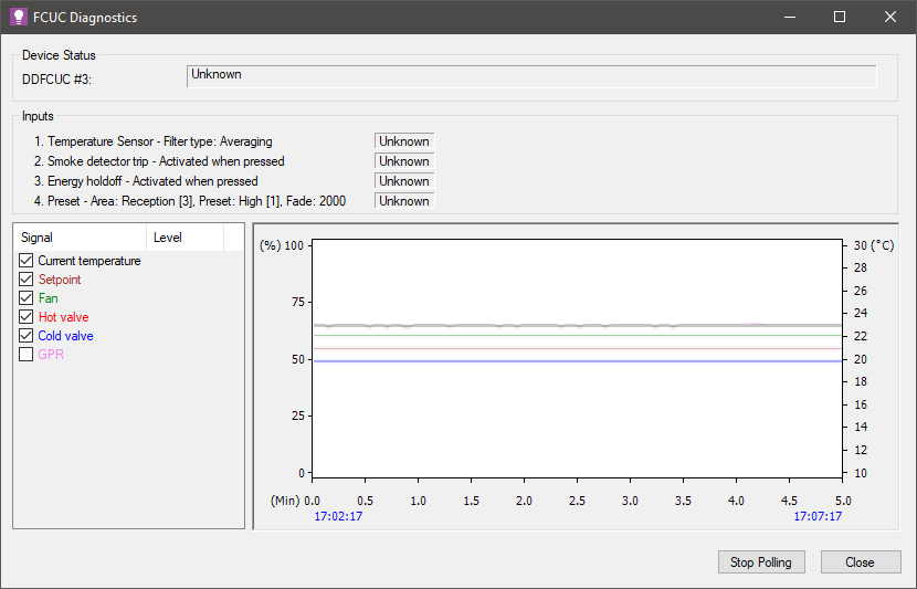
The information displayed here is customised to the configured properties:
-
Setpoint
-
Mode selected
-
Defined inputs
-
Polling period
-
FCUC graph settings
The window initially opens with a blank graph. Polling begins automatically and for each polling period the graph charts the controller status and variables.
To pause and restart polling, click the button.
