DyNet Text Messaging
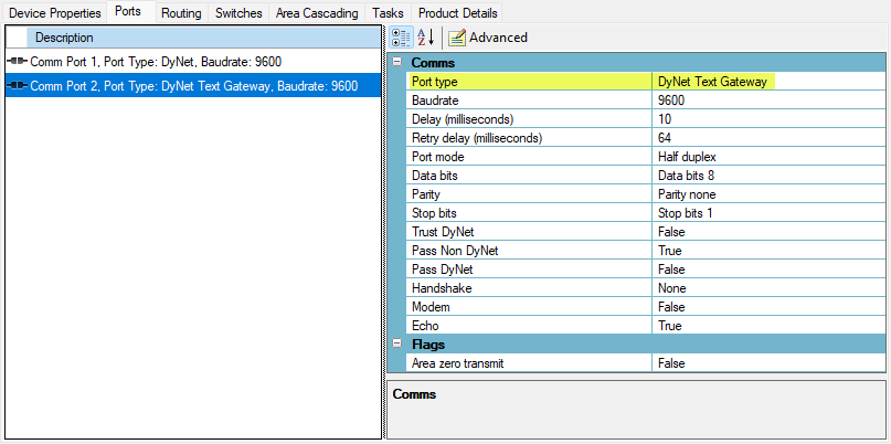
When the Comm Port 2 > Port Type is set to DyNet Text Gateway, the DDNG232 routes messages between Port 1 (DyNet 1) and Port 2 (human-readable text strings). When it receives a correctly formatted command on Port 2 from a connected third-party system, it sends a message on Port 1 to the Dynalite system.
The physical interface uses an 8-bit data packet with 1 start bit, 1 stop bit, and no parity. The default baud rate is 9600. DyNet Text Gateway settings are configurable using the System Builder Ports editor.
| The third-party system must be configured to send and receive DyNet Text messages. |
-
Area preset
-
Monitoring Dynalite network
-
Area off
-
Program to current preset
-
Record and restore preset
-
Reset preset
-
Preset offset
-
Preset status request and reply
-
Linear channel/area control
-
Channel level request/reply
-
Panic/Unpanic
-
Panel disable/enable
-
Remote panel LED control
-
Temperature control
-
Help
The Start Byte
The asterisk (*) Start byte marks the start of each message. All ASCII messages are prefixed with a Start byte.
The command is the first character or keyword after the start byte asterisk. Commands are not case sensitive. There are two command types for each command, short and long.
-
Short command:
*P 10,6,2000↵ -
Long command:
*Preset 10,6,2000↵
The delimiter is the value used between the arguments in the command and can be either a comma (0x2C) or a space (0x20). The delimiter between the command and the first argument must always be a space.
If an argument is not specified in a command string, the gateway will use the argument from the previously transmitted message.
| Command | Description |
|---|---|
[ ] |
Delimits the field between the brackets. These brackets are not actually part of the message. |
P |
Character as a character |
[0x20] |
Single space character |
[36] |
Multiple ASCII string |
↵ |
Carriage return. |
| DyNet Text over RS-232 or RS-485 requires an asterisk as a synchronisation character. This character is optional when using Telnet. |
Area Control
The Dynalite system stores the lighting levels for each preset scene in the load controllers. These can then be recalled from anywhere on the network using a single DyNet message.
Area Preset
Parameters
A multiple ASCII string number representing the area preset level the controllers should go to.
A multiple ASCII string number representing the area the message is being sent to.
The amount of time in milliseconds the system takes to get to the new scene.
| Argument | Actual fade time |
|---|---|
2000 |
2 seconds |
10500 |
10.5 seconds |
120000 |
2 minutes |
Monitoring Dynalite Network
The DDNG232 can translate any DyNet preset message from any device on the network into ASCII.
Parameters
A multiple ASCII string number representing the area preset level the controllers should go to.
A multiple ASCII string number representing the area the message is being sent to.
The amount of time in milliseconds the system takes to get to the new scene.
A hexadecimal value representing the join level of the target area.
Area Off
This message sends all channels in an area to 0%. It is not used often, as Preset 12 is 'all levels at 0%' by default and is more commonly used as an 'off' command. Dynalite wall panel button LEDs will follow this command, so any preset buttons for the area receiving the off command will also turn off their LEDs.
Program to Current Preset
This message makes it possible to save lighting level changes to an area and thus reconfigure presets. The lighting levels are saved over the current preset levels, so it is important to select the preset to be changed before changing any channel levels and sending the program preset message.
| Once this message is sent, the target area’s current preset is permanently overwritten. |
Save and Restore Preset
This message causes all load controllers to save the current preset for every logical channel in the area indicated by the area argument. The preset can then be recalled at any time.
Once the Save Current Preset message is used, the previously saved preset number is overwritten in the controller. By default, the saved preset is Preset 1.
Restore Preset
The 'Restore Preset' message causes all channels in the defined area to go to the saved preset level. If a preset has not been recorded previously the area will go to preset 1.
Reset Preset
If any channels in an area are message, the load controllers will still remember the last preset that area was changed using a message other than a preset in. It is then possible to return an area to its last preset state using the Reset Preset message.
Users can make small changes to a lighting scene using channel level messages, but still return the area to its preset state when required.
Preset Offset
The Preset Offset message causes load controllers with channels within the specified area to change their internal offset value for each affected channel. This value is applied as an offset to any received preset message.
The received preset and the offset value are added together, and the load controller adjusts the appropriate channels to the resulting preset number. By default, the preset offset is 0 and any received preset is the absolute preset number.
This feature is used in areas that require different lighting levels at different times of day or night (e.g. bathrooms and corridors). Preset Offset messages are commonly transmitted to the network automatically by a device with a real-time clock.
A load controller receives "Area 4, Preset 1". The controller had previously received "Area 4, Preset Offset 3". The controller therefore sets the affected channels in Area 4 to Preset 4 (1+3).
Request Current Preset
A third-party device can use the DDNG232 to interrogate the DyNet network for the current state of an area or even a specific channel within an area.
A typical use case would be providing live feedback to a third-party touchscreen to display the current preset for an area.
| The same function is available for individual channel levels using Request Channel Level. |
Current Preset Reply
This is the response from the network to the Request Current Preset message.
Channel Control
There are several messages available to fade a single channel or all channels in an area to a defined percentage level with fade times from 0.1 seconds up to 22 minutes. It is also possible to stop the fade using a Stop Fade message.
Linear Channel/Area Control
Parameters
A multiple ASCII string number representing the logical channel number that the message is to control.
The percentage level the channel is to go to (0-100 as a percentage of maximum output).
A multiple ASCII string number representing the area the message is being sent to.
The amount of time in milliseconds the system takes to get to the new scene.
| Argument | Actual fade time |
|---|---|
2000 |
2 seconds |
10500 |
10.5 seconds |
120000 |
2 minutes |
Request Channel Level
Channel Level Reply
This is the response from the network to the Request Channel Level message.
Parameters
A multiple ASCII string number representing the logical channel number that the message is to control.
A multiple ASCII string number representing the area the message is being sent to.
The percentage level the channel is at or fading to.
The percentage level the channel is currently at.
The join level of the channel being interrogated.
Device Control
Panic
Every area has a configurable Panic preset that can be called using the Panic message. When a control panel sees a Panic message for an area that it controls, it will lock the buttons for that area. This prevents a user from overriding the panic levels. When an Unpanic message is received the area goes back to its previous preset and the buttons on the control panels become active again.
| The commissioning technician can modify the Panic preset level. The default output level for Panic is 100%. |
Panel Disable/Enable
The disable and enable messages allow any buttons configured to an area to be disabled and enabled from a single DyNet message. It is possible on some control panels to set buttons to ignore these messages.
Remote Panel LED Control
In some circumstances it may be necessary to change the state of some or all button LEDs on a remote panel. To do this a DyNet message is sent to the remote panel containing the new LED illumination configuration. It is possible to change the state of specified button LEDs while leaving others in their current state.
Structure
-
*SetL [Device code],[box number],[led numbers] ↵
-
*ClrL [Device code],[box number],[led numbers] ↵
Parameters
This indicates the device type of the panel the message was transmitted from.
| Panel type | Device code |
|---|---|
Antumbra2 |
|
The unique address (for a specified Device Code) of the target device. Each panel has a unique box number. This ID can be provided by the Dynalite commissioning technician.
Indicates the button LEDs the message is targeted at. Each button location has a number on the panel’s PCB. On a 5 button LSP panel the buttons are numbered 1-5. On a 7 button LSP panel the buttons are numbered 1-5, 7 and 9 as buttons 6 and 7 are located over positions 7 and 9 on the panels PCB.
Temperature Control
Commands exist to send and receive temperature control messages. Five logical commands are available, three send messages and two request messages.
Structure
-
*STmpSP [Temperature],[Area],[Join Level]↵
-
*TmpSP [Temperature],[Area],[Join Level]↵
-
*RTmpSP [Area],[Join Level]↵
-
*Tmp [Temperature],[Area],[Join Level]↵
-
*RTmp [Area],[Join Level]↵