Ethernet Access Point
When an EG is configured as a permanent Ethernet access point, it allows any modern browser to communicate with the control system over the Wi-Fi/LAN/Internet. A browser is only able to communicate with one EG at a time, so control is limited to the logical areas set in each EG. However, if a common logical address range is set in each EG then these areas can all be controlled even if they span different EG’s.
To set up the EG as an Ethernet access point, you must first run the ![]() Bridge Configuration Wizard to enable the DyNet Ethernet Access Point routing. Refer to Wireless Commissioning > Adding an IP Address.
Bridge Configuration Wizard to enable the DyNet Ethernet Access Point routing. Refer to Wireless Commissioning > Adding an IP Address.
Basic authentication is provided for web server, Telnet, and FTP connections by adding usernames and passwords in SB.
-
In SB, select the EG and open the Device Properties tab.
-
Enable Web server and/or Telnet (PDEG/PDEB only) applications and related properties.
For security reasons, FTP support has been deprecated in the EG firmware. If visible in SB, you should leave this option disabled. -
Open the Users tab and click to create new users (maximum: 5 per EG).
-
Under User Properties, enter the Name/Password and set the Enable property to True.
-
Under General Permissions, set Web server and/or Telnet to Enabled as needed.
|
Wi-Fi access
For a completely customized interface, mobile apps accessing the connected lighting control system can be manually configured, or the interface can be auto-configured by reading the configuration data (project.xml file) stored in the EG. This saves configuration time and ensures control accuracy on mobile devices.
Once you have completed the logical configuration by entering your area, channel and preset names, you can upload your Project.xml file to the device.
Click ![]() Save to Device after making any configuration changes.
Save to Device after making any configuration changes.
SB has an option to upload a project.xml file by right-clicking the EG and selecting Gateway Actions > ![]() Upload Configuration > Upload Logical Configuration.
Upload Configuration > Upload Logical Configuration.
To control the system, connect the self-configuring mobile app to the network via Wi-Fi and enter the IP address of the EG. The controls in the app auto-configure based on the project.xml file in the EG. The EG supports up to 30 concurrent sessions for mobile apps
| The EG must have an IP address to upload the file. Refer to Wireless Commissioning about adding an IP address. Also, ensure that the EG is on the same subnet as your mobile device. Wireless routers/access points usually give out IP addresses within a certain range, e.g.: 192.168.10.1 to 192.168.10.100. |
| To establish a secure connection when using an app, you may need install the certificate for the relevant operating system on your mobile devices. Refer to Signify Certificate Installation. |
Uploading files
To upload other XML project files to the EG, right-click and select any of the following:
-
 Gateway Actions > Upload Configuration >
-
Upload Logical Configuration
-
Upload Device List
-
Upload Job Properties
-
Upload All
-
To upload a custom web interface, right-click the EG and select Gateway Actions > ![]() Upload Custom Web Pages…. You may decide to delete the existing web pages via the checkbox in the Web Page Upload dialog box. Reset the device to apply the new configuration.
Upload Custom Web Pages…. You may decide to delete the existing web pages via the checkbox in the Web Page Upload dialog box. Reset the device to apply the new configuration.
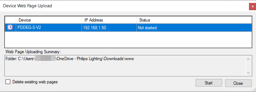
|
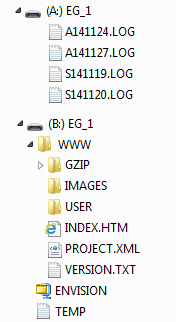
There are two main directories on the device:
-
Directory A
-
Rolling 28-day log files.
-
-
Directory B
-
/WWW
-
/GZIP contains all pre-compressed user interface files for EG. N.B. any uncompressed files referenced from this folder will return browser errors.
-
/IMAGES contains all images (JPG/GIF/PNG) used within the user interface files.
-
/USER a folder containing user defined custom web pages, if any.
-
/INDEX.HTM existing default homepage for the EG web interface.
-
/PROJECT.XML project specific configuration file created on the EG. This file is not present within the installation files.
-
/VERSION.TXT EG user interface build version.
-
-
CGI access
This section describes the Common Gateway Interface (CGI) available from the default or custom web pages. The web pages enable the user to send commands from the device to the network and request information from the network.
| The default web interface is preloaded directly under the B:/WWW folder. |
The CGI has been modelled on the Dynalite Text protocol and Dynalite Tasking syntax. In these protocols many of the command parameters are optional, so if a parameter is not specified then the default value (or the value that was previously specified) for this parameter is used for subsequent CGI requests. Alternatively, you may explicitly specify a value for all parameters each time a command is executed.
-
If your default page is no longer index.htm, then you must change the option in Device Properties.
-
The filename WebPage.cgi is reserved for retrieving webpage data.
-
The filename SetDyNet.cgi is reserved for issuing DyNet commands.
-
The filename GetDyNet.cgi is reserved for retrieving DyNet status.
-
All files names are case sensitive on this device, following Unix and web standards.
-
The ? character is used to initialize a CGI string and the & char is used for delimiting.
Example: 192.168.2.2/SetDyNet.cgi?a=3&p=2
DyNet commands and status requests
Following table lists the HTTP/CGI requests available from the device.
Required parameters are shown in bold.
| Function | CGI request | Parameters | Value Required | Value Range | Description |
|---|---|---|---|---|---|
Preset |
P or PRESET |
A |
Yes |
0 to 65535 |
Also supports special presets: |
Channel Level |
L or LEVEL |
A |
Yes |
0 to 100 |
Channel level in percentage |
Colour Temperature |
CT |
A |
Yes |
0 to 65535 |
Colour temperature in Kelvin |
Program/Save Preset |
PP or S |
L, A |
Yes |
0 to 255 |
Saves the current channel levels to the specified preset |
Start Task |
STT |
- |
Yes |
0 to 255 |
If DC and BN are not provided, the device’s DC and BN will be used. |
Stop Task |
SPT |
- |
Yes |
0 to 255 |
If DC and BN are not provided, the device’s DC and BN will be used. |
Pause Task |
PT |
- |
Yes |
0 to 255 |
If DC and BN are not provided, the device’s DC and BN will be used. |
Enable Event |
EEVT |
- |
Yes |
0 to 255 |
0 = All Events |
Disable Event |
DEVT |
- |
Yes |
0 to 255 |
0 = All Events |
Trigger Event |
TEVT |
- |
Yes |
1 to 255 |
0 = All Events |
Read Task Port Value |
RPV |
- |
Yes |
0 to 255 |
SBP is optional for task sub-port number |
Write on Task Port |
WPV |
- |
Yes |
0 to 255 |
SBP is optional for task sub-port number |
Write on Sub-Task Port |
SBP |
RPV or WPV |
Yes |
0 to 255 |
|
Value to Write to Port |
V |
WPV |
Yes |
0 to 255 |
Specifies the value to write to task port. |
Nudge Up |
NU |
A |
Yes |
0 to 100 |
Channel level in percentage |
Nudge Down |
ND |
A |
Yes |
0 to 100 |
Channel level in percentage |
Ramp Level |
RL or RAMPLEVEL |
A |
Yes |
0 to 100 |
Channel level in percentage |
Stop Fade |
SF or STOPFADE |
A |
No |
||
Current Temperature |
TPTR or TEMPERATURE |
A |
No |
-64 to 64 |
Returned temperature shall be in +/- xx.yy format |
Temperature Setpoint |
TPSP or TEMPERATURESETPOINT |
A |
Set: Yes |
-64 to 64 |
Returned temperature is in +/- xx.yy format |
DALI Driver Runtime Status (See note) |
QBS |
DC, BN, C |
No |
Reply if CN not specified: 0: Lamp failure, driver offline |
|
Preset Offset |
O or OFFSET |
A |
Yes |
0 to 127 |
Set the preset offset for an area. |
Reply Timeout |
REPLYTIMEOUT |
- |
Set: Yes |
200 to 20000 |
This is the amount of time that device will wait for a any request message (when GetDyNet.cgi is used) to get back with a reply. If there is no reply after this time, device will reply with an error back to the client. |
Task Register X |
X |
- |
No |
0 to 255 |
|
Task Accumulator |
ACC |
- |
No |
0 to 255 |
|
Area |
A or AREA |
- |
Yes |
Area: 0 to 65535 |
If no area specified, request is processed for most recent area received and saved by the export. Otherwise channel level for requested area is returned without storing the requested area. |
Join |
J or JOIN |
- |
Yes |
0 to 255 |
|
Channel Number |
C or CHANNEL |
- |
Yes |
0 to 65535 |
|
Number of Physical Channels |
CN |
- |
Yes |
0 to 65535 |
|
Box Number |
BN |
- |
Yes |
0 to 255 |
|
Device Code |
DC |
- |
Yes |
0 to 255 |
|
Fade Time |
F or FADE |
- |
Yes |
0 to 5,242,710 ms |
|
'Get DALI driver runtime status' (QBS)
Example: 192.168.2.2/GetDyNet.cgi?DC=100&BN=13&C=23&CN=3&QBS The reply to this request would include the driver status for channels 23, 24, and 25. |
DyNet commands and status request examples
To control DyNet Areas, DyNet logical commands use the HTTP Set method with the SetDyNet.cgi file. DyNet logical status requests use the HTTP Get method with the GetDyNet.cgi file.
http://192.168.10.10/SetDyNet.cgi?a=3&p=2
This sets area 3 to preset 2. Multiple parameters may be used in the one request; however, only one of them should be of the command type. The response from this HTTP request automatically redirects the browser back to the calling page as detailed below:
<html><body onload=history.back()></body></html>
http://192.168.10.10/GetDyNet.cgi?a=3&p or http://192.168.10.10/GetDyNet.cgi?a=3
The response from this HTTP request contains the state retrieved from the DyNet area.
A single numeric value is returned indicating the current preset or channel level. If the logical entity does not exist a single full stop character "." is returned. If the response shown below is returned from the request, then area 3 is in preset 4:
p=4
http://192.168.10.10/SetDyNet.cgi?a=2&o=6
If the current preset is 4, the reply will be:
p=4 o=6
Reading the current setting:
http://192.168.10.10/GetDyNet.cgi?replytimeout
returns:
replytimeout=200
Now set it to a new value:
http://192.168.10.10/SetDyNet.cgi?replytimeout=2000
(this is typically for wireless devices that can have a very slow response times)
http://192.168.10.10/SetDyNet.cgi?a=2&c=3,j=255&l=25&pp=10
http://192.168.10.10/SetDyNet.cgi?a=2&c=3,j=255&l=25&f=5000
http://192.168.10.10/GetDyNet.cgi?a=2&c=3&j=255&p=4
http://192.168.10.10/GetDyNet.cgi?a=3&c=2&j=255&l
or
http://192.168.10.10/GetDyNet.cgi?a=3&c=2&j=255
returns:
l=23
HTTPS Secure Access
HTTPS provides a secure connection between your browser and an Ethernet gateway.
HTTPS adds two things to HTTP: secrecy and trust. Secrecy is established with an SSL/TLS TCP connection that encrypts the browser’s data communications.
The most common solution for establishing trust, is based on certificates signed by third-party certificate authorities. Typically, a chain-of-trust is established for a server by preinstalling a signed web-server certificate, supplied by a certificate authority (CA) trusted by the client.
Configuring HTTPS
System Builder has the capability to manage certificates, sign certificates, send certificate signing requests and configure users with different access permissions.
There are three web server certificate options for establishing HTTPS access to the gateway:
For most applications it is preferable to create and upload a System Builder signed certificate on the gateway and install the matching root certificate for each client’s browser or app that will access the server.
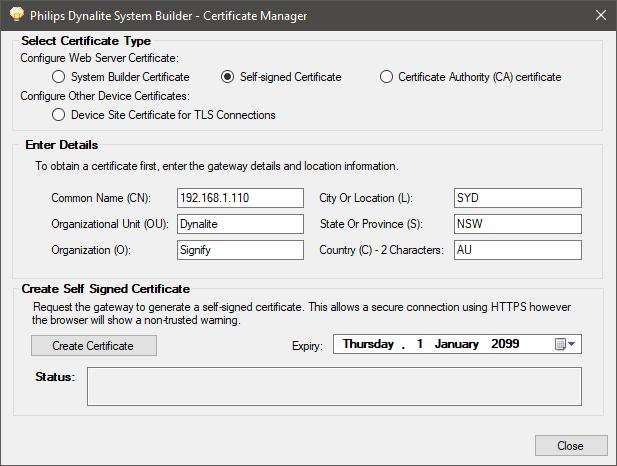
Request the gateway to generate a self-signed certificate. This allows a secure connection using HTTPS however, the browser will show a non-trusted warning.
If you have a domain, you may select a Certificate Authority signed certificate. System Builder will instruct the EG to create a Certificate Signing Request (CSR) from the private key built in to the EG. The CSR can then be sent to a third-party CA. It is the responsibility of the CA to determine if you are trustworthy. They can respond to the certificate signing request by signing your server certificate and sending you the result. You then upload the signed certificate onto your EG. The signed certificate usually does not need to be installed for each client as third-party CA’s are already known to most browsers, however there may be ongoing costs with this option.
|
-
Connect SB to the EG over Ethernet.
-
Right-click the EG and select Gateway Actions >
 Manage Certificate…
 -
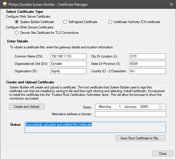
Enter the gateway details and location information.
-
Click Select Certificate Type > System Builder Certificate.
-
Click the button. After 1-2 minutes, System Builder creates a signed certificate file on the EG. Restart the EG to apply the certificate.
-
Click the button to save the (
.cer) file to your PC. -
Right-click the security certificate (
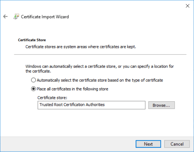
.cer) file on your PC and select Install Certificate to open the Certificate Import Wizard. -
In the wizard, click the button, then select Place all certificates in the following store and set the Certificate store to the Trusted Root Certification Authorities folder.
-
Click the button and button to complete the import wizard. The wizard displays a security warning.
-
Click the button to install the certificate. The wizard shows a message that the import was successful.
-
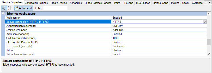
In Device Properties > Ethernet Applications > Secure connection (HTTP/HTTPS) select HTTPS from the dropdown list.
-
Click or press F12 to upload your changes to the EG.
-
Connect SB to the EG over Ethernet.
-
Right-click the EG and select Gateway Actions >
 Manage Certificate…
 -
Enter the EG details and location information.
-
Click Select Certificate Type – Self-signed Certificate.
-
Click the button. After 1-2 minutes, System Builder creates a self-signed certificate file on the EG. Restart the EG to apply the certificate.
-
In Device Properties > Ethernet Applications > Secure connection (HTTP/HTTPS) select HTTPS from the dropdown list.
-
Click or press F12 to upload your changes to the EG.
-
Connect SB to the EG over Ethernet.
-
Right-click the EG and select Gateway Actions >
 Manage Certificate.
 -
Enter the gateway details and location information.
-
Click Select Certificate Type – Certificate Authority (CA) certificate.
-
Click the button. After 1-2 minutes, System Builder creates a certificate signing request file on the EG.
-
Click the button to save the (
.csr) file to your PC and send the CSR file to a CA for signing.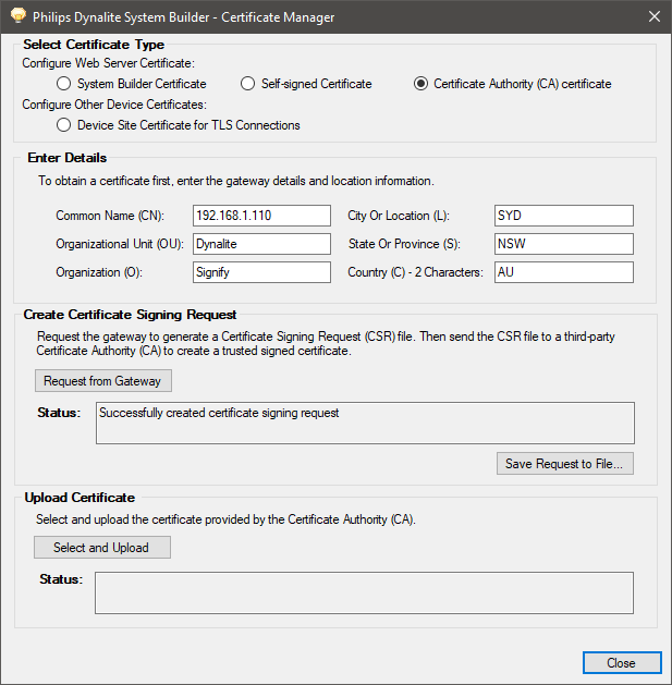
-
After the CA returns the signed certificate, click the button, select the certificate file (
.pem) and click . System Builder uploads the file to the EG. Restart the EG to apply the certificate. -
In Device Properties > Ethernet Applications > Secure connection (HTTP/HTTPS), select HTTPS from the dropdown list.
-
Click or press F12 to upload your changes to the EG.
Establishing a HTTPS Connection
To confirm your signed certificate, open the EG homepage in your browser by entering https:// followed by the EG’s IP address. When a browser connects to the gateway’s web server, it will prompt you to enter your username and password (as set up in SB in the EG’s Users property editor).
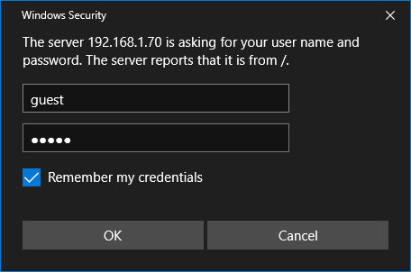
The browser will verify that your server certificate has been signed by a trusted CA, and establish a secure connection with the EG web server.

To see whether a website is safe to visit, you can check the site’s security information by looking at the security status to the left of the URL bar. The browser will alert you if you cannot visit the site safely or privately with a visual indicator such as a red address bar and/or an error message warning that the server certificate is not trusted. Secure HTTPS connections are indicated with a closed padlock icon.