DMX Configuration
The DACM (v3 or later) can be configured for DMX output instead of DyNet, enabling control of up to 64 DMX channels from a single device.
In DMX mode, the DACM operates as normal and supports all of the same functions, but output is limited to DMX channel level messages.
| Once a DMX configuration is saved to the device, it can no longer communicate with DyNet devices or networks unless placed in bootloader mode. |
| Never connect a DMX UI to a Dynalite system, as it may flood the network and interfere with DyNet communication. |
Creating a DMX UI in System Builder
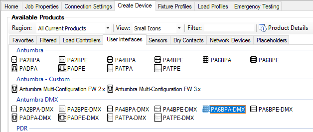
To create a DMX panel in System Builder, select it from the Create Device tab or right-click an existing UI in System View and select Configure > ![]() Factory Set… to reconfigure it for DMX.
Factory Set… to reconfigure it for DMX.

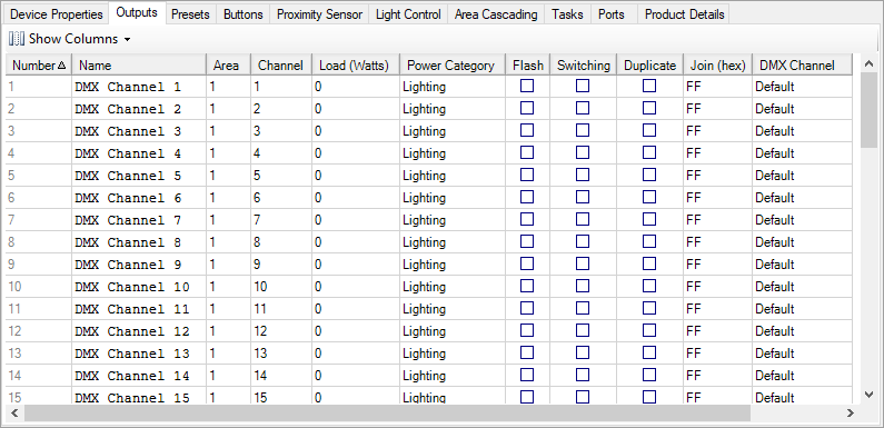
The Channel Editor tab shows 64 Logical Channels that are each mapped to the corresponding DMX channel number by default.
To assign a new DMX channel to a Logical Channel, click on its entry in the DMX Channel column and enter the required DMX channel number.

The default configuration includes only one Logical Area, but the Logical Channels can be sorted into more areas as desired. This allows area preset commands to affect multiple DMX channels simultaneously, such as controlling all of the lights in a room, or grouping the channels that control each color for a single RGB fixture.
| Logical Area and Channel management is outside of the scope of this document, see the System Builder Quick Start Guide for more information. |
Refer to topic Button Functions and Sub functions for examples of the available preset and channel level commands. Almost any lighting requirement can be handled by the Channel Level, One Touch, Preset, and Ramp functions.
The DACM is still capable of running local tasks for more complex control scenarios, provided that the required Logical Areas and Logical Channels are mapped correctly.
Making configuration changes in Bootloader mode
Bootloader Mode temporarily disables DMX and restores DyNet communication to allow configuration changes from System Builder. You will require a direct link between System Builder and the DACM, via either a DTK622 PC Node or a shared DyNet network.
This procedure can be performed with or without the application module connected to the DACM. In this mode the panel does not respond to button presses, and the screen on the AntumbraDisplay remains blank.
-
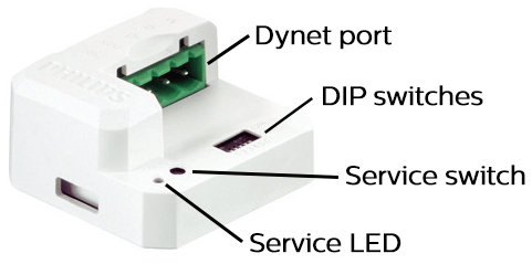
With the DACM unplugged, use a paperclip or pen to hold down the service switch.

-
With the switch held down, connect the DyNet cable to the DyNet port.
-
When the red service LED turns on, release the service switch.
The DACM is now able to communicate with System Builder. You can make configuration changes or factory-set the device back to DyNet. Once all changes are complete and saved to the device, simply disconnect the DACM and reconnect it to its original network to resume normal operation.