BACnet Data Point Testing
After completing the PDDEG-S BACnet Configuration Wizard, the final step before handover to the BMS contractor is to check that each point is functioning correctly.
Using System Builder and a BACnet client such as Yet Another BACnet Explorer (YABE) or BACnet Discovery Tool (BDT), test each point by:
-
Setting a data point value from the BACnet client and monitoring the message in the Network Log (writing).
-
Setting a data point value from SB and monitoring the corresponding data point value in the BACnet client (reading).
The Virtual Panel and  DyNet Packet Sender enable you to send out the DyNet messages that are read by the BACnet client (Click
  or press Alt+F9 to ensure the panel is configured to the area selected in the Areas View).

The example commands are mostly in DyNet1 format and need to be sent from the serial spur. Depending on your specific setup, these commands might need to be routed through a translation gateway first before reaching the PDDEG-S BACnet gateway.
| You can have two SB windows open at the same time, one connected to the (IP) trunk and one to the (serial) spur. In case messages remain unanswered, check your trunk and spur routing and how each instance of SB is connecting to the system. |
Totals
Total Offline Devices
Read data point
The PDDEG-S aggregates the count of offline devices and reports this via the Total Offline Devices BACnet point. It is NOT necessary to enable the individual Device Offline Status points for each device. It will monitor the individual device’s status in the background.
Example for a project with 250 devices:
-
1 point if only the Total Offline Devices point is enabled on project level
-
251 points if both Total Offline Devices (project level) and individual Device Offline Status points are enabled.
The PDDEG-S will poll device status automatically on an hourly basis. Besides this, it will monitor sign-on requests and replies to track device status. If a sign-on request remains unanswered 3x, the PDDEG-S will consider the device to be offline until a sign-on reply is received. It does not track the Device Offline Metric messages.
Total Driver and Lamp Faults
Read data point
The PDDEG-S aggregates the count of driver and lamp faults and reports this via the Total Driver and Lamp Faults BACnet point. This point will monitor the status of all drivers and lamps in the background. It is not required to enable the individual points to get an aggregated result.
The Total Driver and Lamp Faults point relies on the DALI channel replies. See Driver status and Lamp status for more detail.
Alarms
Offline Device Alarm
Read data point
This point is a logical function of the Device Offline Status points. If one or more devices are offline, this point will be True. If no device is offline, the value will be False. It is not mandatory to have Device Offline Status enabled for individual devices.
The PDDEG-S will poll device status automatically on an hourly basis. Besides this, it will monitor sign-on requests and replies to track the device status. If a sign on request remains unanswered 3x, the PDDEG-S will consider the device to be offline until a sign-on reply is received. It does not track the Device Offline Metric messages.
Driver or Lamp Fault Alarm
Read data point
This point is a logical function of the Driver Status and Lamp Status points. If one or more of these points reports a fault this value will be True. If no Driver or Lamp is offline, the value will be False. It is not mandatory to have Driver status and Lamp status enabled for this BACnet point.
The Driver or Lamp Alarm point relies on the DALI channel replies. See Driver and Lamp status for more detail.
System Manager Offline Device Alarm
Read data point
When System Manager is present it can monitor offline devices. If one or more are offline, it will set the System Manager Offline Device Alarm BACnet point to True.
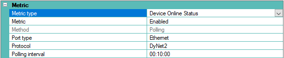
In contrast to the Offline Device Alarm, this does not depend on other BACnet points or the hourly PDDEG-S polling mechanism. Instead, it relies on the PDDEG-S Metrics editor Metric > Device Online Status to be Enabled and, in the SM Configuration tool, Site Settings > System Settings > Enable roll call polling set to True.
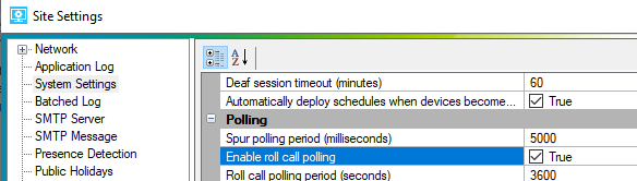
When System Manager is configured to detect offline devices, this information needs to be forwarded to the BACnet gateway. In the SM Configuration tool, Site settings > System Settings > Polling > Send DALI driver and Lamp failure aggregated for the whole site must be set to True.

If devices go offline, it will be reported with the Report Device Offline command. Add this command to the DyNet Sender, toggle the 6th byte between 0x00 and a higher value, and check that the System Manager Offline Device Alarm updates accordingly:
-
Report 0 Device Offline:
1C,00,04,47,00,00,FF -
Report 1 Device Offline:
1C,00,04,47,00,01,FF
| This command is sent via area 0 (zero). If an extra PDEG is added when you have separate BMS and Dynalite networks, Area zero transmit must be enabled on the extra PDEG (on both trunk and spur ports) and on the PDDEG-S Comm port. |
System Manager Driver or Lamp Fault Alarm
Read data point
When System Manager is present it can monitor driver and lamp failures. If one or more have failed, it will set the System Manager Driver or Lamp Fault Alarm BACnet point to True.
In contrast to the Driver or Lamp Fault Alarm it doesn’t depend on other BACnet points and doesn’t use the hourly PDDEG-S polling. Instead, it relies on the regular DALI Driver and Lamp Status polling. Device Properties > DALI > DALI Enable DALI status polling and ballast failure alarms must be enabled in DALI controllers and SM Configuration tool, Site settings > System Settings > Polling > Enable DALI ballast polling must be set to True.

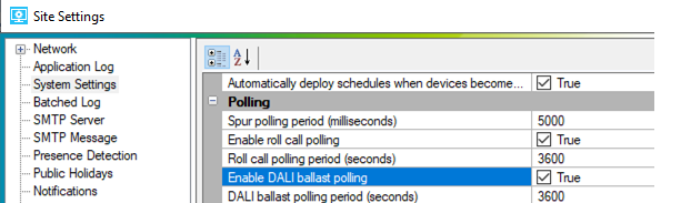
When System Manager is configured to detect driver and lamp status, this status needs to be forwarded to the BACnet gateway. In the SM configuration tool, Site settings > System Settings > Polling > Send DALI driver and Lamp failure aggregated for the whole site must be set to True.
If drivers or lamps go offline, it is reported with the Report area status command. Add this command to the DyNet sender, toggle the 6th byte between 0x00 and a higher value, and check that the SM Driver or Lamp fault alarm updates accordingly.
-
Report 0 Ballast (Driver) Offline:
1C,00,01,47,00,00,FF -
Report 3 Ballast (Driver) Offline:
1C,00,01,47,00,03,FF
| Driver and Lamp status are reported separately on the BACnet side. |
Logical Areas and Channels
Preset
Write data point
In the BACnet client, enter a preset number in an area’s Preset object. Although the BACnet point type is an analogue value it only accepts integers (1,2,3,4 etc.). Observe the preset change in the lighting and in the Network Log.
Preset number range: 0 to 65534. Max number of presets supported varies per controller (e.g., DDBC120-DALI supports 64 presets). Panic preset message uses preset 65534.
-
Recall Preset:
1C,<Area>,64,00,00,00,FF

Current Temperature
To keep the BACnet Current Temperature point in sync, select one device (with a temperature sensor) in an area and set Device Properties > Temperature > Broadcast temperature to Enabled. This will report the actual temperature when the Max trigger time expires, and/or if the temperature change has exceeded the Delta value when the Min trigger time expires.

Read data point
In Areas view, select an area. With the DyNet Packet Sender, add Request Actual Temperature. Click  Send. Observe the matching area’s Temperature data point value change in the BACnet client.
-
Request Actual Temperature:
1C,<Area>,0C,49,00,00,FF -
Reply Actual Temperature:
1C,<Area>,0C,4A,11,1B,FF (+17.27°C)
Temperature Setpoint
Write data point
In the BACnet client, enter a temperature in an area’s Temperature Setpoint object. Observe the temperature setpoint change in the Network Log.
-
Set Temperature setpoint:
1C,<Area>,0D,48,14,00,FF

Channel Level
The PDDEG-S will automatically update the channel level points with every preset change. It does not require specific polling to keep the channel level points up to date.
When a preset is received, it initially updates the logical channel levels according to the Project.xml file. After that, roll call polling of the logical channel level values can take over 1 minute to update. In case the channel levels in the PDDEG-S are not in sync with load controller preset levels due to a Program Preset or Save Current Preset function, the logical channel level roll call polling will keep it in sync (with a small delay).
Write data point
In the BACnet client, enter a level in an area’s Channel Level object. Observe the lighting channel level change and in the Network Log.
Channel level range: 0% to 100% (use integer values only)
-
Recall level:
1C,03,FF,80,FF,64,FF

Drivers
Driver Status
The PDDEG-S will listen to DALI status messages which are send by the DALI controllers. When DALI controller > Device properties > DALI > DALI status polling and ballast failure alarms is enabled, the DALI controller will automatically report changes in DALI Driver status.
When querying the driver status from the Outputs editor or when hovering over a DALI fixture icon on the floor plan, this triggers a request to poll the channel status. The channel status reply will update the BACnet driver status points.
Read data point
A driver status fault can be forced by removing a luminaire from the DALI bus and waiting for the internal polling of the DALI controller to detect and report the status change. Connecting the luminaire back will clear the failure. This will result in the following DyNet messages:
-
Report Channel status:
5C, <device code>, <boxnumber>,4D,02,<channel number>,01 (driver online) -
Report Channel status:
5C, <device code>, <boxnumber>,4D,02,<channel number>,02 (driver offline)
This can also be simulated from the SB DyNet Sender if the drivers are known from the DALI controller Outputs editor. Copy and paste the command above into the DyNet sender and update the device code, box number and channel number accordingly.
Lamp Status
The PDDEG-S will listen to DALI status messages which are sent by the DALI controllers. When DALI controller > Device properties > DALI > DALI status polling and ballast failure alarms is enabled, the DALI controller will automatically report changes in the DALI lamp status.
When querying the driver status from the Outputs editor or when hovering over a DALI fixture icon on the floor plan, this triggers a request to poll the channel status. The channel status reply will update the BACnet lamp status points.
Read data point
Forcing a lamp failure must not be performed due to safety concerns, as it requires the lamp/LED board to be disconnected from a (powered) DALI driver.
If a lamp failure must be tested it can be simulated by using the DyNet sender. It would require the physical channels to be present in the DALI controller and assigned to a fixture icon on the floor plan. When the commands below are sent, the status change will be reflected in the fixture icon on the floor plan and on the Lamp status BACnet points. Make sure the device code, box number and channel numbers are updated to match your setup.
-
Report Channel status:
5C,<device code>,<boxnumber>,4D,04,<channel number>,00 (lamp failed) -
Report Channel status:
5C,<device code>,<boxnumber>,4D,04,<channel number>,01 (Lamp OK)
Devices
Channel Runtime
To automatically update channel runtime in the PDDEG-S, set Metric to Enabled and set Method to Polling.

Depending on your trunk and spur topology, the parameters for Port type and Protocol may need to be changed. For a single spur project (devices connected via RS-485), select Comm port and DyNet1 respectively. When the PDDEG-S is installed as a building supervisor and communicating with other devices via Ethernet, select Ethernet Client and DyNet2. Either way, ensure that the polling commands are being answered before checking the BACnet point value updates.

Device Offline Status
The PDDEG-S will poll device status automatically on an hourly basis. Besides this, it will monitor sign-on requests and replies to track the device status. If three sign on requests in a row go unanswered, the PDDEG-S considers the device to be offline until a sign on reply is received. It does not track the Device Offline Metric messages.
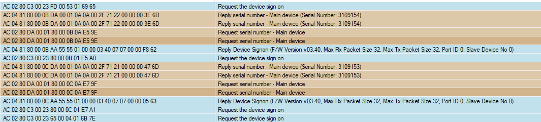
Devices may have physical outputs which control luminaires on different floor plans. In those cases, the device will be listed under the floor plan that holds the first physical channel of the controller. Ethernet devices are listed under the Unplaced Devices folder.

Light Level (Lux)
To automatically update this BACnet point, select a sensor in System view, open the Light Control - Closed Loop editor, and set Reporting to Enabled. When enabled, the sensor reports the lux level every Max reporting period, and/or if the light level change has exceeded the Delta value (Lux) when the Min reporting period expires.
| Legacy sensors do not natively support this feature. In these rare cases, a task is required to push the lux values automatically. |


Read data point
In the DyNet Packet Sender, select Reply PE Cell status - Filtered Raw LL and click Send. Observe the sensor’s Lux Level point value change in the BACnet client.
-
Lux Level:
AC,05,83,B2,00,01,B2,00,01,00,04,01,00,00,00,00,00,41,20,00,00,00,E2,00
| DALI devices are not currently supported. |