On-Site Configuration
-
System Installation Guide
-
Room layout (showing lights, UIs, sensors, and other services)
-
Electrical drawings (including elevation drawings to show UI locations)
-
ID1 DIP switch settings table
-
ID2 DIP switch settings table
-
Room IP address table
-
Snagging list
Installation
Prepare a System Installation Guide for the installers. Then, prior to installation, brief the installers on the system installation tasks.
-
Instructions to connect and test room and corridor devices, wiring recommendations, and cable length estimates.
-
The DIP switch settings tables to instruct how to set the DIP switches for each room controller.
-
Antumbra multi-configuration DIP switch settings table.
-
Drawings to identify correct location of UIs (and UI buttons) and sensors (sensor coverage diagrams).
-
Wiring instructions (in-room wiring run).
-
Hotel room numbers from the hotel operator (not from the builder).
-
Device labels to identify the room devices and floor gateways.
| On the room controller, it is important that the DIP switches are set before powering on. If DIP switches are changed, reset the controller by holding the service switch for more than four seconds. It can take up to 30 seconds for the controller to come back online. |
Room controllers may be room-specific (if using static IP addresses), but all other room devices are room-agnostic. This allows the contractor or hotel engineering to easily swap in spare devices/parts as needed.
Floor gateways are floor-specific due to static IP addressing. Floor gateways must be installed according to the building’s IT requirements.
Testing and validation of the installation is the responsibility of the installer. Suggested installer tests include:
-
Service switch on each controller (as per front label)
-
Walkthrough test
-
Emergency lighting test
Saving device configurations
| These steps only apply to devices that were not preconfigured in the factory. |
-
Connect SB via Ethernet or serial connection.
-
Create and upload certificate.
-
Run the Bridge Configuration Wizard.
-
Save device configuration and check the Ethernet trunk connection.
Refer to the steps in Add Floor Gateway.
-
Open the room configuration and select the DDRC-GRMS-E in System view.
-
Connect SB via Ethernet or serial connection.
-
Adjust the room controller DIP switches.
-
Create and upload the certificate.
-
Change the room device box numbers to match the room profile.
-
Save the configuration to all devices in the room.
Refer to the steps in Create and upload the DDRC-GRMS-E certificate, then complete the steps below.
To save the configuration for the room controller and room devices, you need to open two instances of System Builder.
-
SB with new empty job to change device box numbers.
-
SB with hotel job to be used as a reference for the room configuration device box numbers and to save the configuration to each device.
-
Go to each room and plug the commissioning PC into a USB PC node, then plug the USB PC node into a DyNet socket that is connected to an RS-485 network serial port.
-
Ensure the room controller DIP switches are set for the correct room and all room devices are powered up.
-
Launch SB with the hotel job
-
Launch a second instance of SB with a new empty job and connect using a serial connection.
-
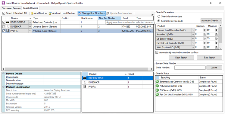
Click
 Insert Devices from Network ( Ctrl+L ) and:
-
Search by device code for the required room devices
OR -
Sign on each room device by pressing the service switch or holding down a UI button
OR -
Turn the room circuit breaker OFF then ON (all devices will power up and sign on).
Signed-on devices appear in the Discovered Devices window.
-
-
Enter a new box number for each room device to match the box number in the hotel job room configuration.
-
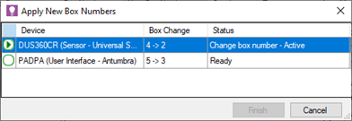
Click
 Change Box Numbers. The Apply New Box Numbers window opens and saves the new box numbers to the listed devices.
-
If applicable, Create and upload the DDRC-GRMS-E certificate.
-
Close the Discovered Devices window, then close this instance of SB.
-
Open the hotel job file.
-
Click File >
 Manage Room Profiles to open the Room Profiles dialog box.
 -
Click the Room Mapping tab.
-
Click
 Add to add a room mapping entry (you can add all entries for the floor).
 -
In the new row, enter the details for the current room (or copy and paste from an existing row then modify as needed).
-
Click the OK button to save the room mapping table and close the Room Profiles window. The Master Configuration is rebuilt and now includes the new room.
-
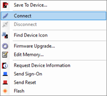
In the Master Configuration System view, right-click the room controller for the room you are configuring and select
 Connect….
Ensure the Machine Connection Settings are configured to use a serial connection (SB lower right corner showsConnected-COM).
-
Select the room controller and all room devices by holding the Ctrl key and clicking each device.
-
Right-click one of the selected room devices and select
 Save to Device.
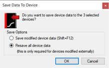
 -
In the Save Data To Device window, select Resave all device data and click OK.
The full configuration data is saved to each device.
-
Select each room device and click
 Send Device Sign-on ( F6 ).
 -
Check the Network Log to verify that each device responds correctly.
-
Click
 Disconnect.
 -
Click
 File Save to save the job.
Acceptance testing
Server room
Check that IT equipment has been installed and configured correctly. All Ethernet gateways must be patched and powered up. The patching panel may be in the IT server room.
Guestroom
The integrity of the cabling and device installation must be verified before accepting the handover from the installer. Installation and electrical testing of rooms is entirely managed by the electrical contractor. You must verify that all devices have been installed according to instructions and the installer has executed the electrical tests and signed off that all tests have passed.
-
Snagging list
-
Open the hotel job file/database.
-
Connect SB to the network, either via the Ethernet trunk or directly to a floor gateway.
-
Add the room mapping entries for the rooms you will be testing.
-
Starting from the first room, right-click the Ethernet bridge (if using) and select
Send Sign-on.
Note the response from the Network Log. -
Right-click the DDRC-GRMS-E and select
Send Sign-on.
Note the response from the Network Log. -
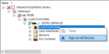
Under the DDRC-GRMS-E, right-click each device folder and select
Sign-on all Devices.
Observe the Network Log for responses from each device.
-
Record the responses from all room devices in the Snagging list.
-
Repeat for each room in the hotel.
| Be aware of where SB is connected. On the trunk side of the gateway, you will see addresses with the floor offset. On the spur side of the gateway, you will see addresses without the floor offset. |
| If DIP switches are duplicated on two DDRC-GRMS-Es then in SB you will see devices with duplicate box numbers. Alternatively, if you set all rooms to the same room status, such as, DND or MUR, and filter your Dashboard Control Center floor view to show this status, then the duplicate room number will be missing. |
| If two floor gateways have duplicate offsets, you will be controlling rooms on two different floors at the same time. Recheck the Bridge Address Ranges for each floor gateway. |
Device box numbers are already preprogrammed in the factory. Except for DALI localization and problem investigations, there should be no need to attend rooms. Everything is either predefined or worked on from a central location. This reduces your per-room labor allocation to approximately 20 minutes per room (5 minutes each for testing, problem reporting, retesting, and for unforeseen support requirements).
-
Device Test - When the contractor believes a floor is complete, it is handed to the System Engineer to test rooms from the server.
-
Contractor Snagging - After testing, report any devices you can’t reach to the contractor to check and remedy.
-
Device Retest - After snagging, the rooms are retested by signing on all the devices (controllers, sensors, and user interfaces)
-
Dashboard Room Setup - Once rooms pass all tests, they are added (partial or full floor) onto the dashboard. This acts as the handover to the hotel operator.
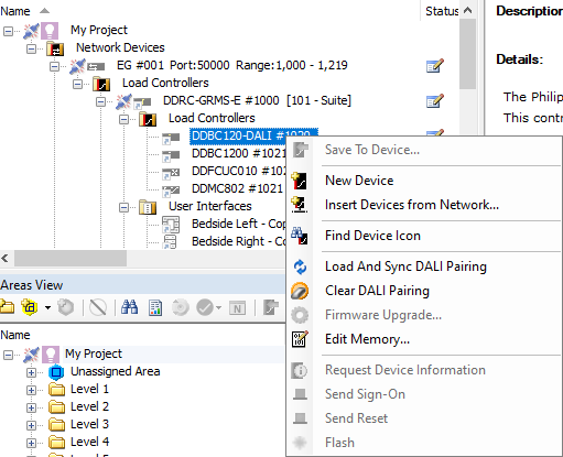
DALI Pairing
| If you have a DDBC120-DALI or DDBC130-DALI controller, the DALI drivers must be localized using the standard DALI enumeration process in System Builder, or via the dashboard - refer to Multiroom Dashboard > Management Luminaires. |
|
To resolve issues where duplicate or incorrect DALI addresses are seen in the dashboard’s Manage Luminaires page, follow these steps: Clear DALI controller addresses:
|
|
To load and sync DALI addressing for DALI drivers have been enumerated and paired by running SB in the room. Follow these steps: Load and Sync DALI Pairing:
|