Create Hotel Job File
The System Engineer produces a hotel master job file by adding the floor gateways, room profiles, mockup room jobs, room alerts, and room mapping.
| To use the Multiroom Dashboard and API with your mockup room, you must create a hotel job with at least one room and install a licensed copy of Multiroom System Manager. Later when on-site, the System Engineer will use this hotel job file to complete the hotel configuration during acceptance testing. |
-
Mockup room sign-off sheet (release for manufacturing)
-
Mockup room job files
-
Hotel Job file
-
Room Controller IP address table (not required if using Dynamic IP addresses)
-
Floor Gateway IP address table
-
DIP switch settings table
-
Site private key text file (must be kept secure)
Add floor gateway
Each floor gateway is configured with a unique IP address and floor offset (physical and logical address range), for example, 1000, 2000, 3000 etc. A global logical range is also added to all gateways (areas 65000 – 65005) for logical messages to all rooms.
The Ethernet connections between SM, PDDEG-S, and DDRC-GRMS-E are secured via TLS encryption.
|
Disable the UDP default multicast, unicast, and all other unnecessary protocols and ports before handing over the system to the customer. This is performed automatically when selecting the “Hotel Floor Ethernet Gateway” or “Hotel Room Ethernet Gateway” options in the Bridge Configuration Wizard. For more information on making the system more secure, please refer to the Ethernet Gateway Commissioning Guide. |
-
Secure
-
Port 443 for Trunk connections (System Manager - Floor Gateway)
-
Port 50443 for Floor connections (Floor Gateway – Room Controller)
-
-
Unsecure
-
Port 50000 for Trunk connections (System Manager - Floor Gateway)
-
Port 50003 for Floor connections (Floor Gateway – Room Controller)
-
-
Click File > New and select
 New Empty Job (Ctrl+N).
 -
Enter the Hotel details in the Job Properties Editor.
-
Click
 File Save As > Save As Job File to save the Hotel job to your PC.
 -
Connect SB via an Ethernet cable and TCP/IP address to the PDDEG-S, or via a USB cable and PC Node to the serial port.
-
Click
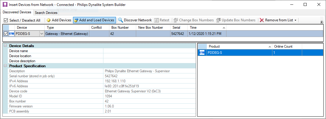
 Insert Devices from Network (Ctrl+L) and select
  Discover Network > Discover Devices over Ethernet or search for the Ethernet gateway, or press the service switch. The gateway appears in the Discovered Devices window.
 -
Click
 Add and Load Devices to add the gateway to the job from the Discovered Devices window. This loads the default device configuration, admin password, and properties.
-
Click
 Save to Device.
 -
Click
File Save to save the job to your PC.
Create and upload the gateway certificate
A Site CA Certificate (Site Private Key) must be first be created or imported into SB. The Site CA Certificate is then used to sign and upload a Device Site Certificate to the PDDEG-S gateways. When SB has a Site CA certificate, it shows a ![]() green lock icon at job level in the System and Building views.
green lock icon at job level in the System and Building views.
SB shows a ![]() green lock icon next to an PDDEG-S or Ethernet device when a Device Site Certificate has been uploaded. This enables SB/SM and Ethernet devices to securely connect to the PDDEG-S gateways via a secure TLS TCP connection.
green lock icon next to an PDDEG-S or Ethernet device when a Device Site Certificate has been uploaded. This enables SB/SM and Ethernet devices to securely connect to the PDDEG-S gateways via a secure TLS TCP connection.
If the lock icon on an EG shows a ![]() warning icon, then check the tooltip as it will indicate either:
warning icon, then check the tooltip as it will indicate either:
-
Device site certificate configured but Site CA used to sign the device site certificate is not found on this machine. System Builder will be unable to securely connect to this device. Ensure correct Site CA certificate is imported into this machine with the Tools menu, Set Site CA Certificate option.
-
Device site certificate configured but doesn’t match Site CA configured in job. System Builder will be unable to securely connect to this device. An updated device site certificate should be signed and uploaded to the device.
-
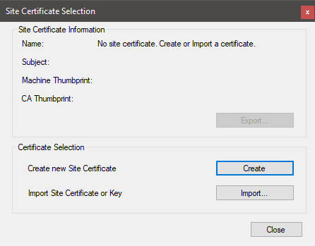
From the Tools menu, select
 Set Site CA Certificate to open the Site Certificate Selection window.
 -
If starting a new job, click the Create button to create a new site certificate.
-
After creating a new site certificate, you will be prompted to Export the site certificate and save it in a secure location.
-
For additional security when exporting the site certificate, you must enter a password. This password will be required by anyone importing the site certificate into another machine.
-
-
If someone has already started commissioning any of the devices and already created a site certificate, they will need to export the certificate from their machine. You can then import the site certificate to any machines used to commission or connect to secure Ethernet devices.
| The Site CA certificate is stored in your machine, not in the job file. To allow another machine to commission the same site you must securely send the job file, the Site CA Certificate, and the password. |
| Having a lock icon in SB, a gateway, or a device simply means you have created and uploaded a certificate. You still need to configure the secure connections (with the Bridge Configuration Wizard) and save to device before you can connect securely. |
| The certificate placed in SM, the PDDEG-S, and the DDRC-GRMS-E must be signed by the same Site CA Certificate. |
| The certificate can be uploaded over a TCP/UDP or serial connection. |
-
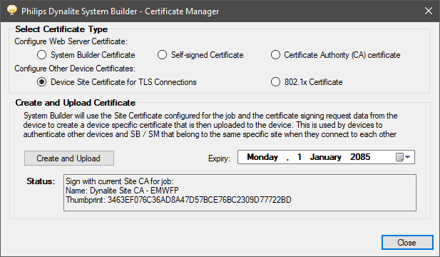
Right-click the floor gateway in System view and select
Manage Certificate. -
Select Certificate Type > Device Site Certificate for TLS Connections.
-
Click the Create and Upload button. After a minute or two, System Builder creates and uploads a signed certificate file to the gateway.
-
Click the Close button.
Configure the floor gateway connections
We strongly recommend configuring secure connections between System Manager, the PDDEG-S, and the DDRC-GRMS-E.
-
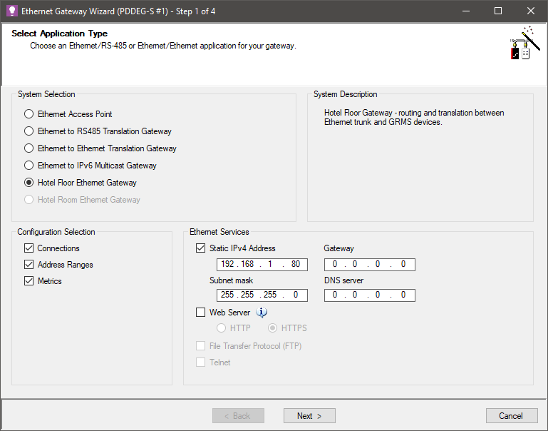
Right-click the floor gateway in System view and select
 Bridge Configuration Wizard (Alt+W).
 -
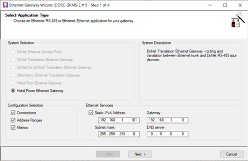
Select Hotel Floor Ethernet Gateway.
-
Select Static IPv4 Address and enter IP Address (and Gateway and Subnet mask if required).
-
Leave Web Server unchecked.
-
Click the Next > button.
-
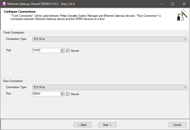
Under Trunk Connection, select TCP IPv4, Port 51443 and Secure checkbox.
(For unsecure Trunk Connection, select TCP IPv4, Port 50000) -
Under Floor Connection, select TCP IPv4, Port 50443, Secure checkbox, and click the Next > button.
(For unsecure Floor Connection, select TCP IPv4, Port 50003).
-
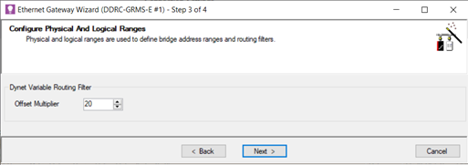
Click the
 Add Physical Range icon and enter the Offset, Min, and Max values.
 -
Click the
 Add Logical Range icon and enter Offset, Min, and Max values.
 -
Click the
Add Logical Range icon again and enter Offset = 0 (zero), Min = 65000, and Max = 65005 for the global areas.
Ignore any popup message boxes. -
Click the Next > button.
An SB Technician License is required to enter an address range without an offset. 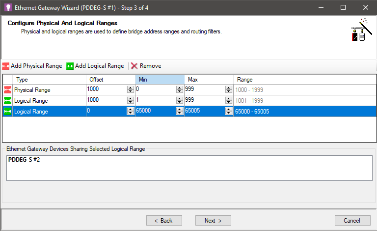
-
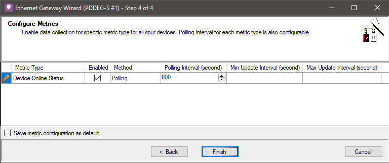
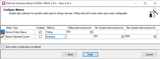
Click the Next > button to accept the default metrics on the spur.
You can adjust the Polling Interval if required, otherwise proceed to the next step.
-
Click the Finish button, then click the Yes button to confirm.
-
Record the box number and IP address in the Floor gateway IP address table.
-
Click
Save to Device. -
Click
File Save to save the job to your PC.
| The Hotel Floor Ethernet Gateway option in the Bridge Configuration Wizard disables the default UDP multicast connection when saved to the gateway. This means SB must now connect to the gateway using a secure Ethernet trunk connection. |
Add alternative floor gateway
Network gateway redundancy is provided by adding an alternative floor gateway for every primary floor gateway in the project. The two floor gateways must be in different locations to ensure adequate redundancy.
The primary gateway and the alternative gateway are both connected via an Ethernet trunk connection. If a floor gateway fails, then SM and the DDRC-GRMS-E room controller connections will switch over to the other gateway (maximum switchover time is 2 minutes). The current connection is maintained (unless the alternative gateway fails) even if the other gateway comes back online.
Both floor gateways are listed in the job’s master configuration. However, only the primary gateway will show the connected DDRC-GRMS-E controllers in the network device tree. The two gateways should be similarly named and have identical port, routing, and metric configurations. It is recommended to commission the primary floor gateway and then copy the configuration to the alternate floor gateway.
Only these properties differ between the primary and alternative gateways:
-
User settings
-
IP address
-
Box number
-
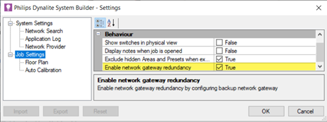
Set Settings > Job Settings > Behavior > Enable network gateway redundancy to True.
-
Copy and paste the primary gateway to create the alternative gateway.
-
Select the alternative gateway, click Device Properties and set Is alternative gateway to True.
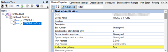
-
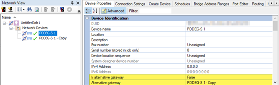
Open the primary gateway’s Device Properties tab and select the Alternative gateway from the dropdown list.
|
The security certificate must be uploaded to both gateways. Additionally, both the primary floor gateway and alternative floor gateway IP addresses must be entered in the DDRC-GRMS-E Gateway Mapping Editor. Refer to Configure gateway mapping. |
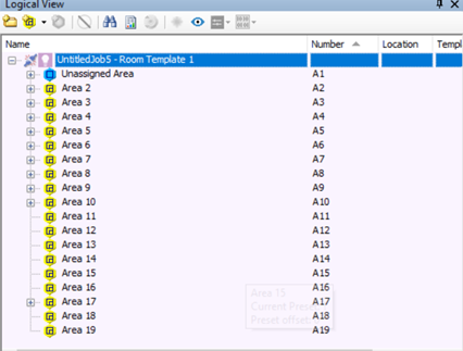
Add global areas
Global areas are used for system-wide messages to indicate day/night or current season.
-
Click the
 Areas View tab.
 -
Click
 Insert New Folder and name it Global Areas.
 -
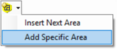
Click the
 Insert New Area dropdown list and select Add Specific Area.
-
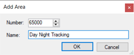
In the Number field, enter 65000.
-
In the Name field, enter Day Night Tracking.
-
Click the OK button.
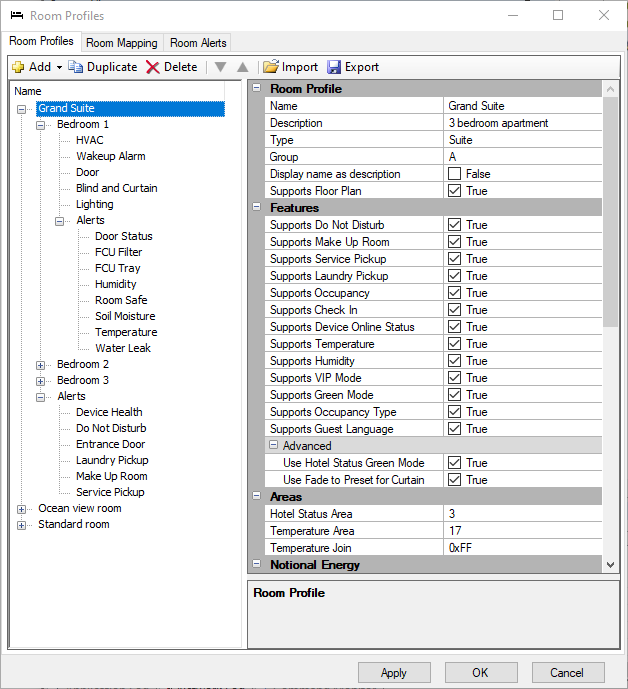
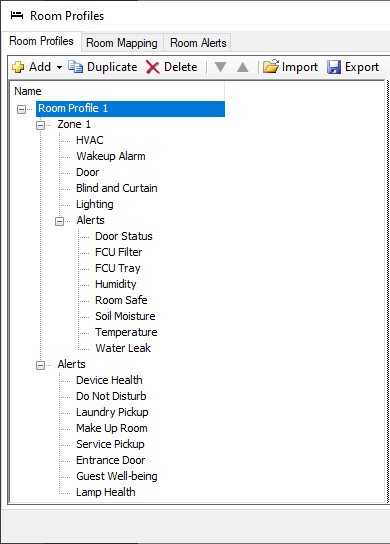
Add room profiles
Since most hotels have a limited number of room profiles, this eliminates much of the repetition involved in adding rooms with identical configurations. The Room Profiles editor determines which zones, features, areas and services are supported by each room profile. These are displayed in the dashboard and are also available on the API.
The following room profile limitations affect the dashboard room view:
-
1 service of each type per zone (only 1 wake-up service per suite)
-
3 items per tile
-
5 different service types (HVAC, Wakeup Alarm, Door, Blind/Curtain, Lighting)
-
10 tiles per service
-
Click
 File > Manage Room profiles to open the Room Profiles dialog box.
 -
Click
 Add > Room profile.
You can also Duplicate,
  Delete,
  Import, and Export room profiles.
 -
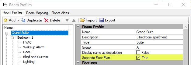
With the room profile selected, enter a Name, Description, and Type for easier identification.
The Type property determines the how the room is grouped and displayed on the dashboard.
-
Enter a Group name if you have many room profiles. This property groups room profiles under submenus in SB > File > Open Room Configurations.
-
If applicable, select Supports Floor Plan to enable the floor plan drawing to be shown on the dashboard. This is mainly used for public areas and larger suites. Refer to Add a room configuration floor plan.
-
You can set Display name as description to True to show the Room Description (from the Room Mapping Table) instead of the room number on the dashboard. This is typically used for public areas.
-
Select the supported room features for your project, e.g. Do Not Disturb, Make Up Room, Laundry Pickup, Service Pickup, Humidity, Temperature for a guestroom. This ensures that only relevant information is displayed on the dashboard’s Room View page. You can also set the Hotel Status Area and Temperature Area to the area numbers reserved for these functions.
-
Default Hotel Status Area = 3
-
Default Temperature Area = 17
-
-
Enter the estimated room profile base power in Watts for each room state (this should be estimated by the hotel’s electrical engineer/specifier).
-
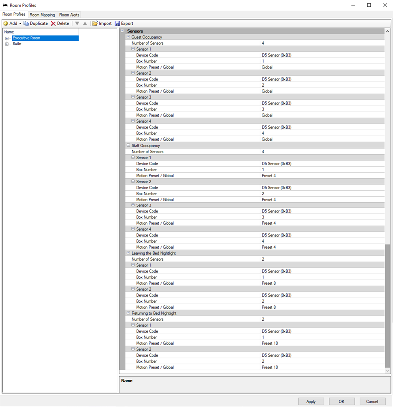
Enter sensor information to allow dashboard users to update occupancy timeouts and AntiStumble nightlight timeouts for each room profile (See Multiroom Dashboard > Room & Suite Profiles).
Select the number of ceiling sensors and AntiStumble sensors used in your room profile:ExampleA suite with:
-
2 x ceiling sensors (Bedroom + Bathroom)
-
2 x AntiStumble sensors (Bed Left and Bed Right)
Would have:
-
Guest Occupancy:
4 -
Staff Occupancy:
4 -
Leaving the Bed Nightlight:
2 -
Returning to Bed Nightlight:
2
-
-
Enter each sensor’s Device Code, Box number, and Motion Preset under each applicable category.
As in the example above, you may need to reenter one sensor’s info under multiple categories. This allows each sensor to support different timeouts under various occupancy and room status conditions. These timeouts are set via the dashboard’s Configuration > Room & Suite Profiles > Room settings.
-
With the room profile highlighted, click
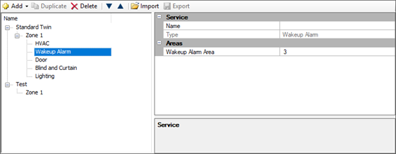
Add > Zone to create as many zones as the room requires. Each room profile must have at least one zone. You can enter a name for each zone for easy identification. A zone can contain one of each type of supported service:-
HVAC
-
Wakeup Alarm
-
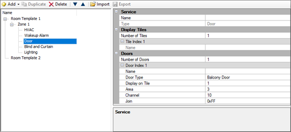
Door
-
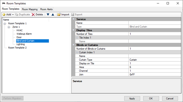
Blind and Curtain
-
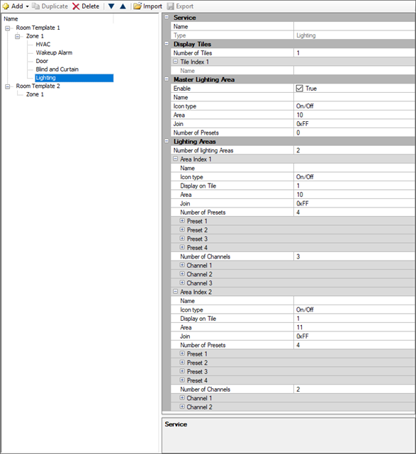
Lighting
Separately serviced areas (such as rooms with their own HVAC units and balcony doors) require a separate zone.
-
-
With the zone selected, click
Add > Service to add each required service to the zone. Enter a name for each service for easy identification. The Name property is displayed in the service’s tile in the dashboard Room View. Use the  Up and
  Down arrows to reorder the zones and services in the dashboard Room View.
 -
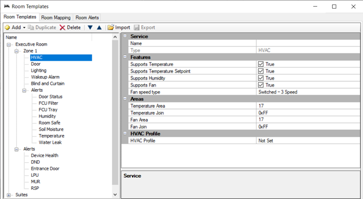
Select each service (refer to the Example Services Properties screenshots below) to configure the Features and logical Areas.
-
Click the
Export button to save a room profile to an editable XML file. This enables profile sharing across multiple sites.
To load an exported profile, click the Import button and follow the prompts. -
Click the OK button to save your changes and close the Room Profiles window.
Example Services Properties
HVAC
-
Default Temperature Area = 17
-
Default Fan Area = 17
|
If using a floor plan for this room profile, select Service > HVAC Service in Floor Plan. 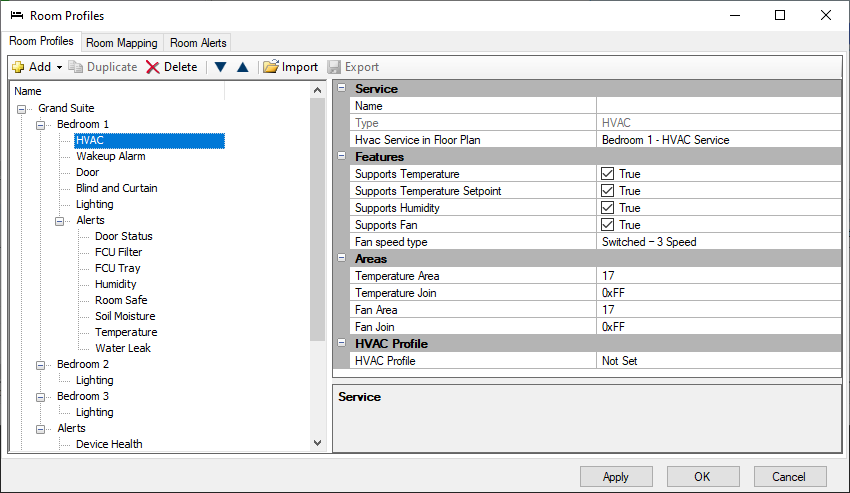
|
| Switched 3-Speed Fan | Variable 5-Speed Fan | Variable 10-Speed Fan |
|---|---|---|
Preset 1 - High |
Preset 4 – Auto |
Preset 4 – Auto |
| For more information on fan speeds and HVAC profiles, refer to Configure notional energy. |
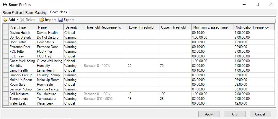
Define and add room alerts
Various room alerts can be specified for each room profile. They are displayed in the dashboard room view and are available on the Hotel Integration API. Each room alert is added to a room profile and applies to either the entire room profile or to a zone within the room profile. To trigger a room alert, the corresponding hardware must first be configured in the room.
-
Click File >
Manage Room Profiles to open the Room Profiles editor. -
Click the Room Alerts tab.
-
Click
Add and select the required room alert. -
Edit the Name, Severity, Minimum Elapsed Time (before the alert is triggered) and the Notification Frequency.
For Humidity, Soil Moisture, and Temperature, you must enter the Lower Threshold and Upper Threshold values. -
Room Alerts can be added more than once with different parameters as required.
Click the beginning of the row to Delete a room alert. You can also Export and Import room alerts to/from an XML file.
-
Click the Room Profiles tab.
-
Select the required Room Profile or Zone.
-
Click
Add > Alert and the select the required alert. The alert will be grey if it has already been added. -
Click the Apply or OK button.
| To enable the Dashboard to identify offline DALI drivers/lamps, DALI drivers must be placed into zones in the room controller’s Outputs editor. Lamp Health must be enabled. |
|
Disabled room devices will:
|
Room Alert Descriptions
Guestroom Alerts
| Room Alert | Description |
|---|---|
|
Indicates the online/offline status of room devices after the minimum elapsed time. Requires the Device Online Status metric. To exclude devices, set Device Properties > Device Identification > Room device enabled to False. |
|
Indicates when the entrance door has been left open for the minimum elapsed time. Requires a room controller or DLLI8I8O Entrance Door Dry Contact Input and/or Access Control System message. |
|
Indicates the current room status after the minimum elapsed time (requires a UI, Dashboard, or PMS to set the room status): |
|
Indicates that the room has remained occupied but no-motion has been detected for the minimum elapsed time. Default = 24 hours. |
|
Indicates that a DALI driver or lamp is offline. |
Zone Alerts
| Room Alert | Description |
|---|---|
|
Indicates when a balcony door has been left open for the minimum elapsed time. Requires a Balcony Door Dry Contact Input. |
|
Indicates the FCUC filter is dirty after the minimum elapsed time. Requires an FCUC Air Filter Dry Contact Input. |
|
Indicates the FCUC drip tray is full after the minimum elapsed time. Requires an FCUC Drip Tray Overflow Dry Contact Input. |
|
Indicates the humidity is below the Lower Threshold value or above the Upper Threshold value for the minimum elapsed time. Requires a Humidity Sensor. |
|
Indicates that the safe door is closed when guest checks in or out. Requires a room controller or DLLI8I8O Safe Door Dry Contact Input. |
|
Indicates the soil moisture is below the Lower Threshold value or above the Upper Threshold value for the minimum elapsed time. Requires a Soil Moisture Sensor. |
|
Indicates the temperature is below the Lower Threshold value or above the Upper Threshold value for the minimum elapsed time. Requires a network user interface with temperature sensor. |
|
Indicates bathroom water leak. Requires a room controller or FCUC Bathroom Water Leak Dry Contact Input. |
| DALI alerts (Channel offline, Driver/Ballast failure, Lamp failure) do not need to be configured in the Room Alerts editor. Once DALI channels are placed into zones, DALI alerts are automatically displayed in the dashboard. Device Health must be enabled. |
| Alert notifications are set up after SM installation in the SM Configuration Tool > Site Settings. |
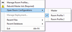
Import mockup room job to room profile
After adding room profiles to the job, you can open them from the File > Open Room Configurations menu. Each room profile is linked to a specific room configuration (mockup room). After making changes to a room configuration, click Rebuild Master Job.
| The room configuration tree has a light purple background color to show that you are viewing a room profile. |
| Areas, System, and Building properties are unique in each room configuration, but Job properties are common. |
| Room profiles that are mapped cannot be deleted. Before deleting, you must first remove the profile from the room mapping table. |
-
Click File > Open Room Configurations and select the required room profile.
-
Click File > Import System Builder Job…, select the job file, and click the Open button to import the mockup room job file for that room configuration.
(You can also manually add the mockup room devices and areas to the room configuration). -
Click the Test button to confirm that there are no device conflicts.
If there are device conflicts, you must correct the mockup room job file before importing. -
Click the Import button.
-
Click the Close button, then click
File Save ( Ctrl+S ) to save the job to your PC before selecting the next room profile. -
Repeat these steps for each room profile in your project.
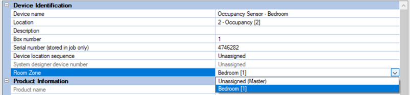
Place devices and channels into zones
The Dashboard’s Control Center page reports device status by zone. User interface and sensor devices must be placed in the room zone where they are located. For single-zone guestrooms, this can remain as Unassigned (Master).
-
Click File > Open Room Configurations and select the required room profile.
-
Select the device (UI or sensor).
-
Click the Device Properties tab.
-
Under Device Identification > Room zone, click the dropdown list and select the zone.
-
Repeat steps 1 to 4 for each UI and sensor in your room configuration.
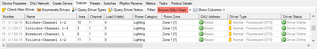
DALI controller channels must have a room zone selected. This enables DALI alerts to be identified by their location in the guestroom.
-
Click File > Open Room Configurations and select the required room profile.
-
Select the DALI controller (the DDBC120-DALI and DDBC320-DALI are supported).
-
Click the Outputs editor tab.
-
In the Room Zone column for each lamp driver, click the dropdown list and select the zone.
| If you have one or more DDBC120-DALI or DDBC320-DALI controllers in a room/suite, the DALI drivers need to be localized using the Multiroom Dashboard. For more information refer to Multiroom Dashboard > Management Luminaires. |
| For security reasons, the DDBC320-DALI Ethernet port must be disabled. |
Add a room configuration floor plan
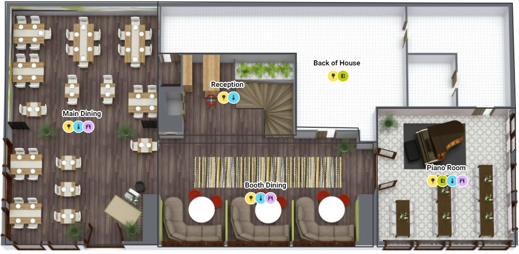
If you have selected Supports Floor Plan in the Room Profile settings, then you can add a floor plan drawing and associated fixtures and devices to the corresponding room configuration. The floor plan will be displayed within the room view on the Multiroom Dashboard.
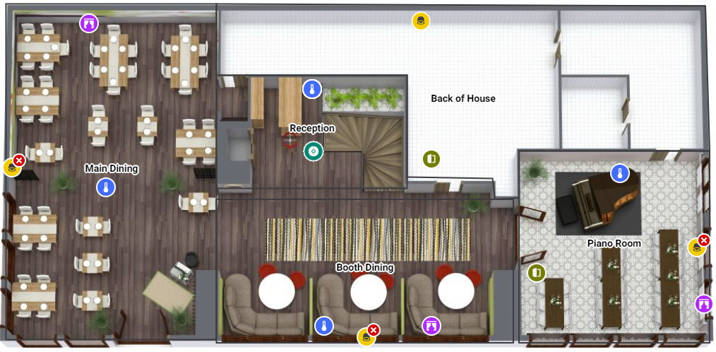
To view the floor plan in the Dashboard, the user can open the Monitor & Control tab, click the ![]() Floor Plan icon in the top right corner, and then select one of the following two views:
Floor Plan icon in the top right corner, and then select one of the following two views:
-
Service & Health
-
Lights & Devices
Light fixtures and devices need to be placed within a zone in their actual location on the floor plan. However, service and health icons are automatically created and placed in the appropriate zone based on the services selected in the Room Profile > Zone Properties.
The following service and device icons are shown on the dashboard:
| Service & Health | Lights & Devices |
|---|---|
|
|
| Note that a floor plan drawing must be cropped to only show part of the floor plan for the specific room profile. To crop the floor plan please use relevant software applications that can handle PDF files and vector drawings. |
|
In File > |
| Currently, user interfaces are not shown on Multiroom Dashboard floor plans. |
-
Click File >
Manage Room Profiles to open the Room Profiles dialog. -
Select the required room profile and set Supports Floor Plan to True.
-
Click or .
-
Click
 Show Floor Plan Window, or
  Float Floor Plan Window ( Ctrl+F9 ).
 -
Click
 Background Image > Select Background Image and select a PDF file that has a cropped floor plan drawing showing the room.
 -
On the floor plan toolbar, select
 Draw Zone Region.
 -
Click and drag a rectangle to draw a zone region for each zone in your room profile.
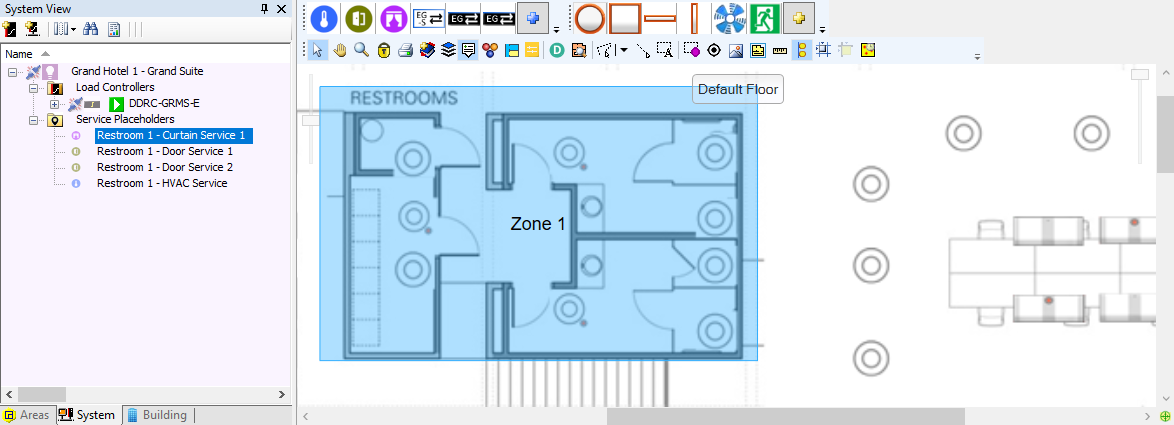
-
Enter the zone region name or keep the default name.
-
(Optional) Select a colour from the colour picker or enter the RGB values and click . You can use this to visually group or differentiate zones.
-
Right-click the zone region to make changes.
If applicable, you can set a new center point to change the location of the zone label (and service icons on the Dashboard). Right-click the zone region and select
 Set Center Point and click in the zone where you want the label to appear.
You can also add to the zone shape by drawing an adjoining zone and giving it the same zone number.
-
From the System View or Building View tree, drag service placeholder devices into the floor plan zone(s) where they are physically located.
-
Drag your DDRC-GRMS-E and other controllers onto the floor plan. These are not shown on the dashboard.
-
In Building View, click the
 Expand icon to show the DDRC-GRMS-E output circuits or DALI controller drivers.
 -
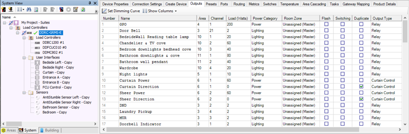
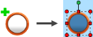 Drag a circuit/driver to a location on the floor plan to add a fixture. The icon shows a green + sign while dragging. You can scale the size of the fixture icon by dragging the red handles.
 -
Right-click a fixture to open the fixture context menu and make other changes to the fixture icon. For example, you can click
 Edit Properties to select a different fixture profile.
 -
Continue dragging circuits/drivers to each zone until you have added all the fixtures in your room.
-
Right-click the controller in System View or Building View and select
Save to Device ( F12 ). -
Click File >
Save ( Ctrl+S ) to save your changes to the job.
Configure notional energy
Notional energy is calculated per room based on the estimated consumption of each load in the room. This data is presented in the Multiroom Dashboard for reporting, analysis, maintenance, and monitoring. Notional energy values are updated hourly on the dashboard and can be aggregated across the whole hotel or per building/wing as required.
Notional energy properties are divided into three power categories:
-
Lighting
-
HVAC (Heating & Cooling)
-
Base power
-
Notional energy load sign-off sheet
Notional lighting power
Notional lighting power uses the estimated maximum load power, channel level, and run-time for lighting circuits to arrive at a notional energy consumption value.
-
Click File > Open Room Configurations and select the required room profile.
-
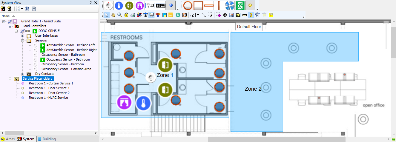
In System view, select a controller and click the Outputs tab.
-
In the Load (Watts) column, enter the maximum power consumption of the load in Watts for each lighting circuit.
-
In the Power Category column, select Lighting for each lighting circuit.
-
Repeat steps 2 to 4 for each controller in the room profile. Ensure that you have included all channels with connected loads.
-
Click
File Save to save the job to your PC.
Notional HVAC power
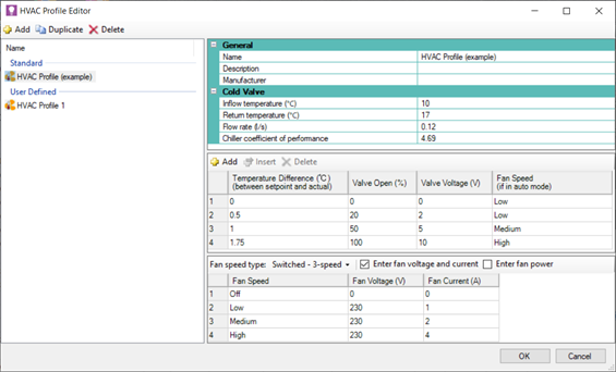
Notional HVAC power uses estimated HVAC energy consumption along with recorded run-time to arrive at a notional energy consumption value. It is calculated from the values entered in an HVAC profile based on manufacturer specifications, fan speed, and the difference between the setpoint and actual temperature.
-
If HVAC status is Cooling or Auto, and actual temp is equal to or higher than setpoint, then the HVAC profile valve table is used for the power calculation. If actual temp is lower than setpoint, the first row of the valve table is used.
-
If HVAC status is Heating, the first row of the valve table is used for the power calculation.
-
If HVAC status is Energy Holdoff or Off, then notional power is zero.
-
Click Tools >
 HVAC Profiles.
 -
Click
Add to add a new HVAC profile (refer to the HVAC profile example for typical values). -
Enter the values in the Cold Valve properties, as provided by the HVAC system consultant.
-
Enter the values in the Valve table, as provided by the HVAC system consultant.
-
Click
Add to add another valve settings row. -
Select a row number and click
 Insert to add a row above the selected row.
 -
Select a row number and click
Delete to delete a row.
-
-
Select the Fan speed type from the dropdown list (3-, 5-, or 10-speed) and select either Enter fan voltage and current or Enter fan power. Enter the values in the Fan Speed table, as provided by the HVAC system consultant.
-
Repeat the previous steps process for each HVAC profile used in the hotel.
-
Click the OK button to close the editor.
-
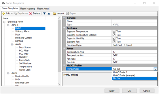
After creating the HVAC profiles, click File >
Manage Room Profiles and select a room profile > zone > HVAC service. -
Select an HVAC Profile for the zone from the dropdown list.
-
Click the Apply button to save your changes, or OK to save your changes and close the Room Profiles window.
Notional base power
Notional base power combines the estimated load for each room state (for non-controlled loads such as minibar, coffee machine, TV, permanently powered outlets, etc.), along with the energy consumption and run-time of plug loads connected to switched outputs, to arrive at a total notional energy consumption value.
Base power has two components:
-
Fixed – Load in Watts specified per room state (non-controlled plug loads).
-
Variable – Load in Watts specified for each circuit with Power Category = Power (controlled plug loads).
-
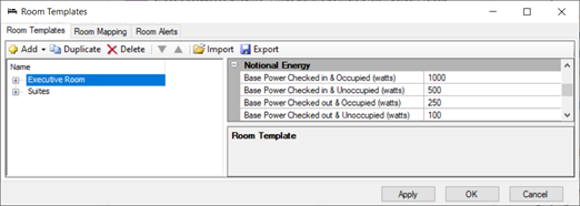
Click File >
Manage Room Profiles and select a room profile. -
In the Notional Energy group, enter the estimated power consumption in Watts for each room state:
-
Base Power Checked in & Occupied
-
Base Power Checked in & Unoccupied
-
Base Power Checked out & Occupied
-
Base Power Checked out & Unoccupied
-
-
Click the Apply button to save your changes, or OK to save your changes and close the Room Profiles window.
-
Repeat the previous steps for each room profile.
-
Click
File Save to save the job to your PC.
-
Click File > Open Room Configurations and select the required room profile.
-
In System view, select a controller and click the Outputs tab.
-
In the Load (Watts) column, enter the maximum power consumption of the load, in Watts, for each power circuit.
-
In the Power Category column, select Power for each power circuit.
-
Repeat the previous steps for each controller. Ensure that you have included all channels that have loads connected.
-
Click
File Save to save the job to your PC.
Configure DDRC-GRMS-E
Create and upload the DDRC-GRMS-E certificate
A Device Site Certificate for TLS Connections must be uploaded to the DDRC-GRMS-E in each room before you can configure a secure connection. To create a Device Site Certificate in the DDRC-GRMS-E, you must first create/import a Site CA Certificate from System Builder Tools > ![]() Set Site CA Certificate. Refer to Create and upload the gateway certificate.
Set Site CA Certificate. Refer to Create and upload the gateway certificate.
| The certificate uploaded to SB/SM, PDDEG-S and GRMS-E must be signed by the same Site CA Certificate. |
| The certificate can be uploaded over a TCP/UDP or Serial connection. |
| The DDRC-GRMS-E must have a box number. |
-
Click File > Open Room Configurations and select the required room profile.
-
Connect SB to the room network.
-
In System view, select the DDRC-GRMS-E load controller and click
Manage Certificate. -
Set Select Certificate type to – Device Site Certificate for TLS Connections.
-
Click the Create and Upload button. After a minute or two, System Builder creates and uploads a signed certificate file to the device.
-
Click the Close button.

Configure gateway mapping
In the room controller, the gateway mapping lists the details of every floor gateway in the project. This enables the installer to select the DDRC-GRMS-E to floor gateway connection by setting the ID2 DIP switches.
-
Click File > Open Room Configurations and select the required room profile.
-
Connect SB to the room network.
-
In System view, select the DDRC-GRMS-E load controller.
Ensure that SB is using the correct box number for the DDRC-GRMS-E - this should match the ID1 DIP switch setting on the controller. If you make any changes the DIP switch setting, reset the controller before proceeding. -
Click the Gateway Mapping tab.
-
Click
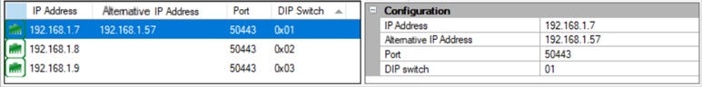
Add to add a gateway mapping row (you can also import and export the rows).
-
Enter the Primary IP4 Address, Alternative IP address and Port (
50443) for the floor gateways and the corresponding DIP switch number. Primary and Alternate gateways must be in the same subnet. -
Repeat for every floor gateway in the hotel project.
| To enable the Alternative IP address, open Tools > Settings > Job Settings > Behavior and set Enable network gateway redundancy to True. |
Configure the DDRC-GRMS-E connections
-
Right-click the DDRC-GRMS-E and select
Bridge Configuration Wizard ( Alt+W ). -
Select Hotel Room Ethernet Gateway.
-
If using DHCP, uncheck the Static IPv4 Address property or enter a static IP address (the Gateway address, Subnet mask, and DNS server address properties are the same as in the Port Editor under IPv4 properties but are not relevant for the DDRC-GRMS-E).
-
Click the Next > button.
-
Select Use Gateway Mapping Port and select the Secure checkbox. Then click the Next > button.
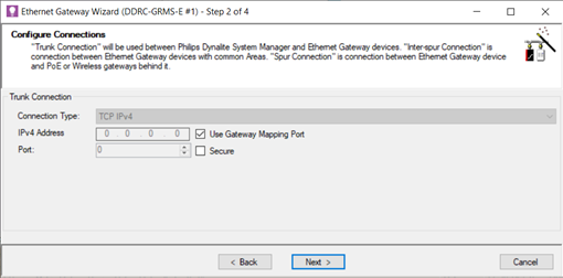
If you do not select Use Gateway Mapping Port, then you can manually enter the IP address and port of a single floor gateway, however you will not be able to change it with the ID2 DIP switches. -
Click the Next button.
-
Click the Next button.
-
Click the Finish button.
-
Press F12 or click
Save to Device. -
Click
File Save to save the job to your PC.
Create device hex files
The device hex files must be sent with the hotel job file to enable device manufacturing and preprogramming.
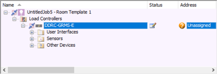
To complete the room profile configuration, you must unassign the box number from the room controller as this will be set by the DDRC-GRMS-E DIP switches.
-
Right-click the room controller and select
 Change Box Number.
 -
Tick the Unassigned checkbox.
-
Click the OK button.
-
Click
File Save to save the job to your PC. -
Repeat for each room profile.
| Check the structure in System view. Ensure all required room devices have been added under the room controller and all logical areas appear as expected. |
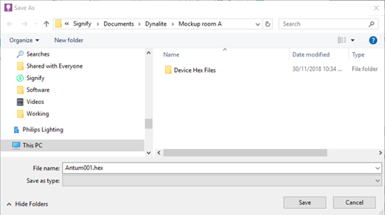
A device hex file is the image that the factory uses to preprogram a room device. Each room device hex file is exported from System Builder and forms part of the package that the system engineer sends to Dynalite.
-
On your PC, create a Mockup Room folder and a Device Hex Files sub-folder.
-
Click File > Open Room Configurations and select the required room profile.
-
Within your selected SB room configuration, select a device to be exported.
-
Select File > Export > Device to Hex File. SB automatically names the file with the device type and box number.
-
Select the required Mockup room and Device Hex Files folder.
-
Click the Save button.
-
Repeat the previous steps for each device in your mockup room.
-
Repeat this procedure for each room configuration.
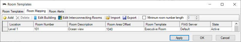
Add room mapping
SB uses the room mapping table to build all the rooms in the Master configuration. You can enter the mapping data manually or import the data from a spreadsheet (.csv file).
The room mapping configures the offsets for each room. Ensure the offsets match the offsets in the floor gateway. For example, a mapping entry for room 101 with an offset of 1040 will require that a floor gateway exists with the offset of 1000.
| At this stage it is only necessary to add the room mapping for your mockup rooms. This enables you to ensure correct functionality before deploying to the complete hotel. You can add to the room mapping table later when acceptance testing each floor at the customer’s site. |
-
Click File > Open Room Configurations > Master to see the hotel job master configuration.
Opening the Master configuration builds the complete hotel structure. It is populated by each room configuration in combination with the room mapping table.
If you have many rooms, when you click File >  Rebuild Master Job, it can take a few minutes for SB to build the Master configuration.
The Master configuration can have different connection settings to a Room configuration. -
Click File >
Manage Room Profiles to open the Room Profiles dialog box. -
Click the Room Mapping tab.
-
Click
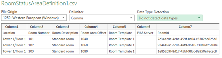
Add to add a room mapping entry, or select the beginning of a row to Delete a room mapping entry. Each room requires:-
Location (building, tower, wing, and/or floor separated by a
/) -
Room Number (Do not enter leading zeros in the room number)
-
Room Description
-
Room Area Offset
-
Room Profile
-
FIAS Server (set to default unless additional FIAS servers are set up in SM)
-
Room Mapping State (Active / Inactive)
The dashboard displays the Room Number for rooms and suites, and the Room Description for all other room types. The data in the Location column creates the folders and floors displayed in the dashboard. These are sorted alphanumerically by default. To change the order, click  Edit Building and manually drag the folders and floors to different positions. The order is indicated by the Index value.
-
-
Add your mockup rooms to the mapping table.
-
Click the OK button to save the room mapping table and close the Room Profiles window.
-
Click
File Save ( Ctrl+S ) to save the job to your PC.
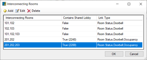
Add Interconnecting Rooms (Room Linking)
Multiroom System Manager allows rooms with interconnecting doors or a shared entrance lobby (vestibule area) to have a common doorbell, room status and occupancy status when connected. The hotel must provide a list of rooms that can be physically connected to each other.
If interconnecting rooms have a shared lobby with an indicator panel, then this needs to be wired to one of the rooms. An area in that room needs to be assigned to the panel to receive hotel status messages from System Manager. If the shared lobby indicator panel has a doorbell button, then this should be configured to send messages to this area.
| If additional hardware is used to connect to the indicator panel, this will require a separate room profile. |
For rooms capable of being interconnected, Dashboard users will see a Link/Unlink Rooms button in the top right corner of the Room view. When linked, the rooms in building and floor view will show the ![]() Linked icon.
Linked icon.


-
Click File >
Manage Room Profiles to open the Room Profiles dialog. -
Click the Room Mapping tab.
-
Click
 Edit Interconnecting Rooms.
 -
Click
Add to add an Interconnecting Rooms entry, or select a row to Edit or Delete that entry.
-
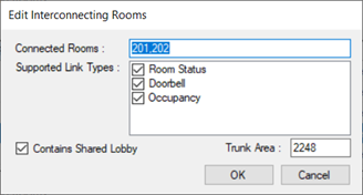
In the Add/Edit Interconnecting Rooms window, enter the connected room numbers.
Each entry requires a list of at least two room numbers, with each room separated by a comma. -
Select the appropriate checkboxes for rooms sharing:
-
Room Status
-
Doorbell
-
Occupancy
-
-
For rooms with a shared lobby, select Contains Shared Lobby and enter the trunk area number for the shared lobby area in one of the adjoining rooms (double-check that it is in the correct range according to the mapping table).
-
Click the OK button.
-
Click the OK button again.
| Supported Link Types > Occupancy must be selected for the Guest Well-Being alert to function in interconnected rooms. |
Behavior of interconnected rooms in System Manager:
-
When Room Status Link Type is enabled and SM receives a set or reset hotel room status message (DND, MUR, LPU, RMS) and the room is currently linked then SM will send the hotel status message back to the currently linked rooms. If a shared lobby area has been configured, then SM will also send the hotel status message to the shared lobby area to update the status on the shared lobby indicator panel.
-
When Room Status Link Type is enabled and rooms are unlinked (either manually from dashboard or automatically when any of the rooms are checked out) and a shared lobby area has been configured then SM will send to messages to reset (clear) all hotel status on the shared lobby indicator panel (DND, MUR, LPU, RMS).
-
When Doorbell Link Type is enabled and SM receives a doorbell on or off message and the room is currently linked, then SM will send the doorbell on or off message to all other rooms currently linked. If a shared lobby area has been configured and SM receives a doorbell message from the shared lobby area, then SM will send the doorbell message to all rooms that are currently linked. If rooms are not currently linked, then no message will be sent by SM. Doorbell messages are DyNet1 opcode
0x6BChannel 1 with Preset 1 for Doorbell ON and Preset 4 for Doorbell OFF. -
When Occupancy Link Type is enabled. If a room that is currently linked reports as occupied, then SM will show all rooms as occupied in the dashboard. Only if all linked rooms are unoccupied shall all linked rooms be shown as unoccupied. When a linked room reports as being unoccupied any linked rooms that are still believed to be occupied by SM shall be sent a Door Closed message to trigger an occupancy check in the room. Shared lobbies are not included in occupancy syncing.
Importing and exporting room mapping
You can add room mapping entries for every guestroom, or click the ![]() Export button to create an editable CSV file and use a spreadsheet editor to complete the room mapping.
Export button to create an editable CSV file and use a spreadsheet editor to complete the room mapping.
-
Under the Data menu, select From Text/CSV.
-
In the Import window, select Do not detect data types and click the Load button.
-
Once the spreadsheet is complete, save your changes.
When on-site at the hotel, import the complete spreadsheet by clicking the ![]() Import button to load the saved file back into the Room Mapping table.
Import button to load the saved file back into the Room Mapping table.
Install System Manager for the mockup room
To use the Multiroom Dashboard and integrations with your mockup room, you must create a hotel job with at least one room and install a licensed copy of Multiroom System Manager. This allows you to check the room logic with the Dashboard and third-party systems.
System Manager Server for the customer will be installed later at the hotel site. For more information refer to System Manager installation.