Off-Site Configuration
Mockup room commissioning process
Multiroom System Manager offers a range of core features and additional feature options. The features chosen by the customer form the basis of the mockup room job file, which contains the configuration for all devices in the specified room profile (mockup room). The STR Template Library job file is considered a starting point and variations are likely in each project.
A single mockup room can cater for different types of rooms if the rooms only have minor variations. Alternatively, you could configure the room and save the job as Room Profile A, then make the appropriate configuration changes and save the job as Room Profile B, etc.
| Before preconfiguring room devices, it is important to identify the installation capabilities and limitations for each room profile. This ensures that all features and options work as expected when installed on site. |
Prepare mockup room
The Electrical Contractor installs the devices in each mockup room, including all network, power, and load connections. Once installed, the System Engineer programs the control features.
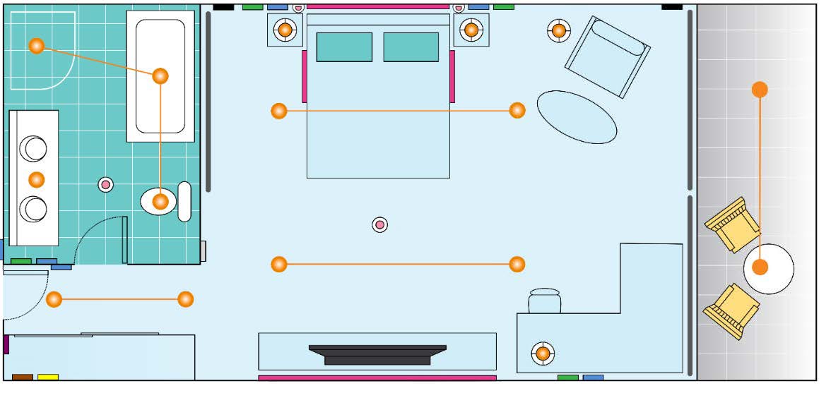
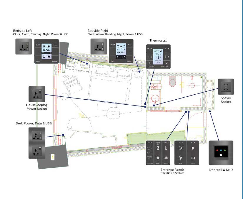
Example Mockup Room
|
Switched luminaire |
|
Occupancy sensor |
|
Dimmed luminaire |
|
AntiStumble sensor |
|
GPO |
|
HVAC Integration |
|
Curtain control motor |
|
Dry contact |
|
Doorbell |
|
AntumbraButton |
|
DMX lighting |
|
AntumbraDisplay |


Example circuit allocation table
| Controller | Channel Number | Description | Circuit Label | Switched | Phase-Cut | DMX |
|---|---|---|---|---|---|---|
General |
||||||
DDRC-GRMS-E |
R1 |
Power Sockets |
GPOs & TV |
1 |
|
|
DDRC-GRMS-E |
R10 |
Doorbell Chime |
n/a |
1 |
|
|
Entrance |
||||||
DDRC-GRMS-E |
R2 |
Entrance Downlights x2 |
L1 |
|
|
3 |
Bathroom |
||||||
DDRC-GRMS-E |
R3 |
Bathroom Cove |
L14 |
1 |
|
|
DDMC802 |
R6 |
Downlights x2 & Pendant |
L2, L3, L4 |
|
1 |
|
Bedroom |
||||||
DDRC-GRMS-E |
R4 |
Bedroom Cove (high) |
L13 |
1 |
|
|
DDMC802 |
R5 |
Bedroom Downlight x5 |
L1 |
|
1 |
|
DDRC-GRMS-E |
R7 |
Bedroom Cove (low) |
L12 |
|
|
3 |
DDMC802 |
R8 |
Bedside Left Reading |
L8 |
|
1 |
|
DDMC802 |
R9 |
Bedside Right Reading |
L9 |
|
1 |
|
DDRC-GRMS-E |
R12, R13 |
Curtain Power & Direction |
L15 |
1 |
|
|
DDMC802 |
E1 |
Night Lights |
L10 |
1 |
|
|
DDMC802 |
E2 |
Floor Lamp |
L6 |
1 |
|
|
DDMC802 |
E3 |
Table Lamp |
L7 |
1 |
|
|
DDRC-GRMS-E |
E4 |
Wall Sconce x2 |
L5, L11 |
|
|
2 |
|
|
Type Count |
|
8 |
4 |
11 |
|
|
Available |
|
4 |
14 |
64 |
|
|
Spare |
|
6 |
0 |
53 |
Fixed outputs
Lighting control
A DDRC-GRMS-E load controller has several fixed switched outputs with various relay ratings. It is recommended to connect the fixed outputs to the following loads:
-
GPOs (General Purpose Outlets)
-
Switched Room HVAC
-
Lighting circuits
-
Curtain/blind motors
Please check the capacity of the relay you plan on using to make sure it is fit for purpose. Room status indicators can be driven by the GRMS digital outputs or a DLLI8I8O. Curtain control channels may also be used for lighting control as required.
Motor control
For direct motor control, channels are connected to mains. For PLC-based motor control, channels can be connected to mains, low voltage, or dry contacts. There are two dedicated motor control relay channels:
-
When selected as a single relay, the output can provide an additional switched lighting circuit.
-
When selected for curtain control, outputs are designed to work in pairs and are interlocked in firmware. First channel energizes/deenergizes the circuit and second channel changes the direction of travel.
| When wiring, note the location of the Normally Open and Normally Closed terminals. |
Modular outputs
As well as controllers with fixed lighting control outputs, multipurpose controllers such as the DDMC802 have modular outputs. Insert the appropriate control modules for the dimmable or switched channels and connect the outputs to their respective loads:
-
Curtain control (interlocked switching)
-
Fan control (variable speed switching)
-
Relay (switching)
-
Driver (ballast) (1-10V/DSI/DALI Broadcast or Addressable dimming, DALI 209 Tunable White)
-
Trailing edge (phase-cut dimming)
-
Leading edge (phase-cut dimming)
| For control modules, you must select the protocol in the Outputs editor > Output Type. |
To configure the modular output channels, install the specified modules and then click the ![]() Query Modules (or Load from device) to set the corresponding lighting protocols. When loads are connected, you can test the connections by sending presets 1 and 4 when channels are still unassigned (in Area 1).
Query Modules (or Load from device) to set the corresponding lighting protocols. When loads are connected, you can test the connections by sending presets 1 and 4 when channels are still unassigned (in Area 1).
Network connections
Dry contact inputs
Connect each volt-free contact to the dry contact inputs. To test that the dry contact input switches are functioning correctly, close the volt-free contact and check with a multimeter at the controller.
UL924 input
Connect the input switch to the UL924 input. To test that the dry contact input switch is functioning correctly, close the contact and check with a multimeter at the controller (UL924 settings are located in Device Properties).
Digital outputs
Connect the outputs to the relevant status indicators. Flash the output channels and check the response with a multimeter.
DMX
Connect the DMX Tx output to the network connection on the DMX fixtures. On the DDRC-GRMS-E there are 64 DMX Tx channels. To check the connection, you must have a load connected to the DMX network and DMX addresses must be within the range of the controller. For more information, refer to the USITT standard on the DMX512 protocol.
Ethernet
Connect the Ethernet cable to the DDRC-GRMS-E controller.
From SB, check that you can discover the controller and receive a sign-on message.
DyNet
Connect the DyNet control cable using a daisy chain connection from the DDRC-GRMS-E Room port to each device in the room.
From SB, connect via Ethernet or RS-485 to the DDRC-GRMS-E and check that you can receive a sign-on message from the room controller and each room device.
Check network integrity by pressing the buttons on the last UI in the daisy chain to send preset 1 and preset 4. Note successful device communication by observing the load controller service indicator flashing rate. New unconfigured sensors respond by blinking faster when receiving an Area 1 message. If lighting loads are connected, they will turn on and off.
In-room third-party integration
Check third-party integration connections, if applicable:
-
AV
-
HVAC
-
Curtains
-
Access control
-
Operations/Housekeeping app
| For system-level integration to function you must have both System Manager and the integrated systems installed and configured. Refer to Install System Manager for the mockup room and Integration. |
When designing a room, you must consider power consumption on the control network. If the design does not include enough controllers, an additional power supply is required to power the sensors and UIs within the room.
Ensure the network cable current does not exceed 2 amps.
| Device | Device current @ 12 VDC |
|---|---|
DDNP1501 |
+1500 mA @ 230 V, +1000 mA @ 120 V |
PDDEG-S |
+300 mA |
DDRC-GRMS-E |
+300 mA |
DDFCUC |
+200 mA |
DDMC802 |
+200 mA |
DDRC810DT-GL |
+120 mA |
DDRC420FR-GL |
+120 mA |
DDBC120-DALI |
+120 mA |
DDBC320-DALI |
+300 mA |
PDEG/PDEB |
-100 mA (+200 mA with external supply) |
AntumbraDisplay |
-60 mA |
AntumbraTouch |
-40 mA |
AntumbraButton |
-35 mA |
Revolution (PDRxE) |
-120 mA |
DLLI8I8O |
-30 mA |
Multifunction Sensor |
-10 mA |
Ultrasonic Sensor |
-80 mA |
Humidity Sensor |
-20 mA |
| Values are subject to change. Please refer to the latest device specification sheets for current values. |
Fan Coil Unit Controller
To control the HVAC, guestrooms are likely to use an integrated HVAC system or a DDFCUC.
| For more information, refer to the Fan Coil Unit Controller Commissioning Guide and DDFCUC Installation Instructions. |
The FCUC has the following connections:
-
Dry contact inputs (selectable x3):
-
Airflow sensor
-
Custom
-
Dirty air filter
-
Drip tray overflow
-
Energy hold-off for window switch
(Not used. Instead, send the balcony door open/close message.) -
Hot water on cold valve
-
Preset
-
-
Input (Dedicated):
-
Temperature sensor
-
-
Outputs:
-
Hot valve actuator (open/close)
-
Cold valve actuator (open/close)
-
Hot valve actuator (0-10 V)
-
Cold valve actuator (0-10 V)
-
Auxiliary feed through relay output (for electric heat relay)
-
| The FCUC temperature sensor input is not used. Instead, temperature sensing is achieved through the Antumbra user interfaces. Please refer to Configuring HVAC and Multi-temperature aggregation. |
Create mockup room job
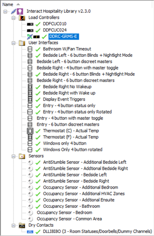
The STR Template Library SB job file contains the standard configuration and tasking for the different room controllers and room devices. The System Engineer customizes the library for each specific room profile to reflect the design of the mockup room. You can place custom tasking in devices other than the room controller.
| The STR GRMS Task can support a single bedroom and bathroom and up to three HVAC areas natively. The HVAC Object task allows up to 17 additional zones of HVAC control. To create additional HVAC areas, you will need to change the Area Offset Multiplier and Box Number Offset Multiplier to a number greater than 20. |
| For larger suites, more bedrooms are configured by placing an AntiStumble task in a sensor for additional AntiStumble zones. Other additional zones can be configured by changing the Area Offset Multiplier and Box Number Offset Multiplier to a number greater than 20. |
Project reference tools
-
STR Template Library
-
Button text/icon images
-
Preset scene definitions
-
Integration descriptions
-
Mockup room features table
-
Room IP address table
-
Room mapping table
-
Floor gateway IP address table
-
Room profile floor plan
Select preconfigured room devices:
-
Open the latest STR Template Library job file.
-
In System View, delete any room devices you do not need.
-
Add more devices to the room controller as required.
-
To change a device type, select
 Change Device Type and select the required device from the list.
 -
To make a copy of a device, select copy and paste. In the Paste dialog box, select the
 Include Task Data checkbox and click the OK/Yes button.
-
-
Enter the mockup room job properties.
-
Click Save As Job File and enter a name for your mockup room job.
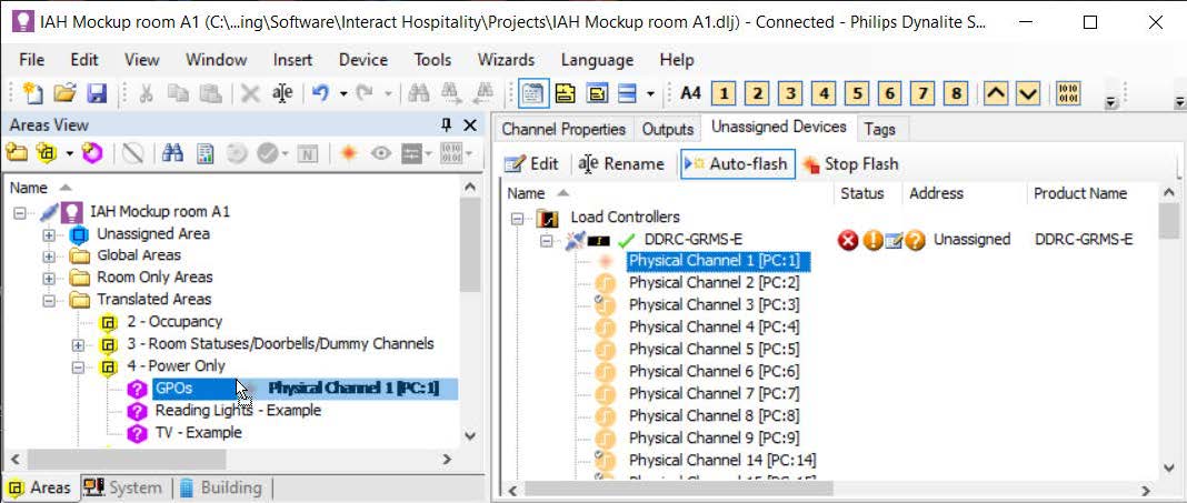
Assign channels and devices to areas
Load controller and device programming follows standard Dynalite programming procedures. The electrical plan indicates the location and type of electrical services in the room, such as user interfaces, sensors, power outlets, blinds/curtains, and lights. From the plan, you can then define the location of logical areas and channels in the room. Interact Hospitality logic relies on assigning circuits and devices to the standard area numbers as shown in the STR Template Library.
The prebuilt logical offsets in the room controller are defaulted to 20 areas. They are allocated to the most common requirements for a guestroom. Although you can customize and change these, we recommend you try to work within this framework to help standardize configuration across projects and to simplify support requests.
There are also a few areas outside of the standard room range:
-
Areas 65000-65005 are used as global areas broadcasting to all rooms.
-
Areas in the 200 range are used as room-only messages that do not leave the room.
Assign circuits to an area:
-
In the Areas view Unassigned Devices editor, drag the controller circuits (physical channels) to a channel in an area or to an area to create a new channel.
 OR
OR -
In the System view room DDRC-GRMS-E Outputs editor, enter the Logical Area and Logical Channel number.
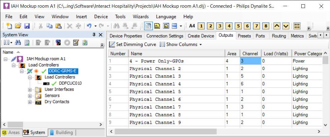
| This is easier to do in precommissioning, before the DDRC-GRMS-E has a box number and offsets are in place. |
| Floor plans are not currently supported in the Multiroom Dashboard but may be used to assist programming. |
Assign devices to an area:
-
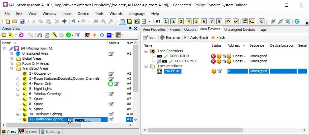
In the Areas view, select the
 Unassigned Area (A1) Unassigned Devices editor and drag a user interface, dry contact, or sensor device to an area
OR -
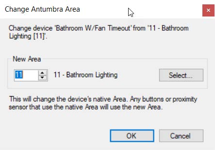
Right-click the device and select
 Change Area….
| The STR Template Library has devices already assigned to the correct area. |
| If you intend to use preset scenes, you must have a room controller or expansion controller with dimming channels. |
| Ensure that you have allocated all required channels. |
Standard area numbers
Global Areas
| Area | Channel | Preset |
|---|---|---|
|
|
Room Only Areas
| Area | Channel | Preset |
|---|---|---|
|
|
Refer to Preset Table in SB |
|
|
|
|
|
|
|
|
|
|
|
|
|
|
| Areas 65000 - 65005 are reserved for receiving building-wide System Manager messages. |
| Areas 200 - 220 are reserved for Room Only Areas. These messages do not leave the room. |
Translated Areas
| Area | Channel | Preset |
|---|---|---|
|
|
|
|
|
|
|
|
|
|
|
|
|
|
|
|
|
|
|
|
|
|
|
|
|
|
|
|
Note: Channels can be added as required. |
|
|
|
|
|
|
|
|
|
|
|
|
|
|
|
|
|
|
|
|
|
|
|
|
Connect System Builder
Connect over Ethernet to a GRMS controller:
-
Connect power to the device(s).
-
Plug the commissioning PC into the Ethernet socket connected to a Gateway, Bridge or Controller with an Ethernet port (either directly or via a switch).
-
If applicable, configure the router to allow IPv6 multicast addresses.
-
Launch SB and connect using the default IPv6 multicast service address or connect using a TCP IPv4 address.
-
Check that you have selected the correct Interface adapter on your PC and make sure it is on the same subnet as the gateway.
-
Click OK. You should see the word Connected in the bottom right of the System Builder window.
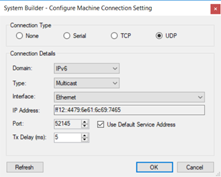
| Devices arrive from the factory with an existing IPv4 address typically based on the hotel’s IT specification. |
|
For security purposes, the UDP Multicast default service address is being replaced. To connect to Ethernet devices, click |
Connect over RS-485 to a GRMS controller:
-
Connect power to the device(s)
-
Plug the commissioning PC into a USB PC node, then plug the USB PC node into a DyNet socket that is connected to the RS-485 network serial port.
-
Launch SB, select the GRMS and connect using a serial connection.
-
Click OK. You should see the word Connected in the bottom right of the System Builder window.
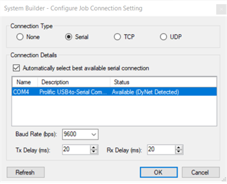
| Pay attention to whether SB is connected to the room or floor port to ensure you have the matching connection settings. |
Assign mockup room devices
-
Set the DDRC-GRMS-E Room DIP switch to 0 (Zero) and reset the device.
-
In System view, select the top of the tree and click
 Insert Devices from Network.
 -
Press the service switch on the room controller or search by device code (0x4E). The room controller now appears in the Discovered Devices list.
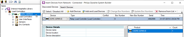
-
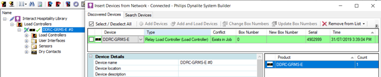
Click and drag the mockup room controller from the Discovered Devices list onto the room controller icon. The room controller in the job adopts the box number of the mockup room controller.
-
Click
 Save to Device.
 -
Select the room controller.
-
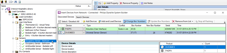
Press the service switch on a room device or search by device code. The room device now appears in the Discovered Devices list.
-
If applicable, you can change box numbers for each room device to be in the range 20-39 by entering the new box number in New Box Number and clicking Change box numbers. The Apply New Box Numbers window opens and saves the new box numbers to the listed devices.
-
Click and drag the mockup room device from the Discovered Devices list onto the device in System view. The room device icon adopts the box number of the mockup room device.
-
Close the Insert Devices from Network dialogue box.
-
Click
Save to Device. -
Repeat steps 6 to 11 for each room device in the mockup room job.
-
Click File > Save as > Save As Job File to save the mockup room job to your PC.
| Third-party sensors are not added to the job as they are included in the tasking. |
Configure addressing
Room Address
To allow for the specified number of areas and devices within each room, the Box number multiplier and Area offset multiplier in the room controller Routing editor are both set to a default value of 20. Maximum value = 255.
The ID1 DIP switch setting is determined by the total value of all ON switches. The image below shows a DIP switch setting (1 + 2 + 16) = 19.

The ID1 DIP switches on the DDRC-GRMS-E set the room controller’s box number and the offsets for devices within the room, using the following formulas:
Room controller box number |
= DIP switch. |
Box number range and Area offset range |
= (DIP switch +1) x multiplier to (DIP switch +2) x multiplier – 1 |
For example, If Room 101, has a room controller DIP switch set to 1:
-
The room controller box number will be = 1.
-
The room device box number range and area range will be
(2 x 20 = 40 to 3 x 20 – 1 = 59) = 40 to 59.
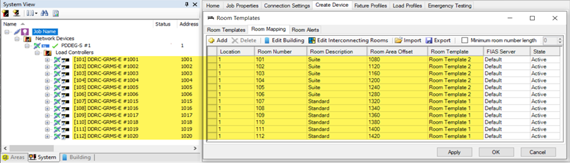
If there is a mixture of rooms with different offsets on a single floor gateway (for example, standard rooms with 20 areas and suites with 40 areas), then it is recommended to minimize area number wastage by allocating low DIP switch values to rooms with the larger offset. You then need to leave a gap in DIP switch values between the larger offset rooms and the smaller offset rooms.
In the example below, DIP switch values 7 to 14 are not used. This enables rooms with a 20-range offset to start their area numbers exactly where the rooms with a 40-range offset finish.
-
used values
-
unused values
| DIP switch | Floor offset | GRMS offset multiplier | Floor start area | Floor end area | Trunk start area | Trunk end area |
|---|---|---|---|---|---|---|
1 |
1000 |
40 |
80 |
119 |
1080 |
1119 |
2 |
1000 |
40 |
120 |
159 |
1120 |
1159 |
3 |
1000 |
40 |
160 |
199 |
1160 |
1199 |
4 |
1000 |
40 |
200 |
239 |
1200 |
1239 |
5 |
1000 |
40 |
240 |
279 |
1240 |
1279 |
6 |
1000 |
40 |
280 |
319 |
1280 |
1319 |
7 |
1000 |
20 |
160 |
179 |
1160 |
1179 |
8 |
1000 |
20 |
180 |
199 |
1180 |
1199 |
9 |
1000 |
20 |
200 |
219 |
1200 |
1219 |
10 |
1000 |
20 |
220 |
239 |
1220 |
1239 |
11 |
1000 |
20 |
240 |
259 |
1240 |
1259 |
12 |
1000 |
20 |
260 |
279 |
1260 |
1279 |
13 |
1000 |
20 |
280 |
299 |
1280 |
1299 |
14 |
1000 |
20 |
300 |
319 |
1300 |
1319 |
15 |
1000 |
20 |
320 |
339 |
1320 |
1339 |
16 |
1000 |
20 |
340 |
359 |
1340 |
1359 |
17 |
1000 |
20 |
360 |
379 |
1360 |
1379 |
18 |
1000 |
20 |
380 |
399 |
1380 |
1399 |
19 |
1000 |
20 |
400 |
419 |
1400 |
1419 |
20 |
1000 |
20 |
420 |
439 |
1420 |
1439 |
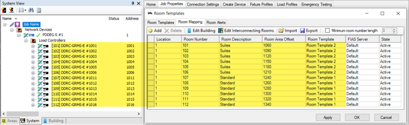
In the example below, DIP switch values 7 to 10 are not used. This enables rooms with a 20-range offset to start their area numbers exactly where the rooms with a 30-range offset finish.
-
used values
-
unused values
| DIP switch | Floor offset | GRMS offset multiplier | Floor start area | Floor end area | Trunk start area | Trunk end area |
|---|---|---|---|---|---|---|
1 |
1000 |
30 |
60 |
89 |
1060 |
1089 |
2 |
1000 |
30 |
90 |
119 |
1090 |
1119 |
3 |
1000 |
30 |
120 |
149 |
1120 |
1149 |
4 |
1000 |
30 |
150 |
179 |
1150 |
1179 |
5 |
1000 |
30 |
180 |
209 |
1180 |
1209 |
6 |
1000 |
30 |
210 |
239 |
1210 |
1239 |
7 |
1000 se |
20 |
160 |
179 |
1160 |
1179 |
8 |
1000 |
20 |
180 |
199 |
1180 |
1199 |
9 |
1000 |
20 |
200 |
219 |
1200 |
1219 |
10 |
1000 |
20 |
220 |
239 |
1220 |
1239 |
11 |
1000 |
20 |
240 |
259 |
1240 |
1259 |
12 |
1000 |
20 |
260 |
279 |
1260 |
1279 |
13 |
1000 |
20 |
280 |
299 |
1280 |
1299 |
14 |
1000 |
20 |
300 |
319 |
1300 |
1319 |
15 |
1000 |
20 |
320 |
339 |
1320 |
1339 |
16 |
1000 |
20 |
340 |
359 |
1340 |
1359 |
Floor Address
Each floor gateway connects via the Ethernet trunk to System Manager and then via an Ethernet spur to the rooms. Each floor gateway is configured with a unique IP address and offset (physical and logical address range) for example, 1000, 2000, 3000 etc.
The floor gateway IP address is configured in the DDRC-GRMS-E by adding a Gateway Mapping Port in the Port Editor. Then, adding a list of all the floor gateway static IP addresses in the Gateway Mapping editor. One floor gateway can then be selected by the ID2 DIP switches on the DDRC-GRMS-E.
| You can enter the Gateway Mapping information in the DDRC-GRMS-E when creating the hotel job or when the IP address of every floor gateway is known. |
Define Room Logic
The STR Template Library in the DDRC-GRMS-E contains all the tasking code to facilitate project programming. Providing a standardized format enables faster installation, commissioning and deployment, easy upgrades, swift support, and consistent documentation to reduce knowledge burden.
To access the template library, select the DDRC-GRMS-E Tasks tab. You can define the logic in the mockup room by first entering the task template settings – Activate features, Areas, Task Controls, Languages, HVAC controls, HVAC Temperatures, Doorbell settings, Automation Settings and Sleep Settings. Then you can modify the configuration of each feature for your specific project.
-
Startup Task
-
logical_watcher_task
-
occupancy_area_task
-
status_area_task
-
nightlight_area_task
-
bedroom_lighting_area_task
-
primary_hvac_area_task
-
secondary_hvac_area_task
-
tertiary_hvac_area_task
-
primary_hvac_energy_holdoff_timer
-
secondary_hvac_energy_holdoff_timer
-
tertiary_hvac_energy_holdoff_timer
-
resume_hvac_preset_processing_task
-
vip_refresh_task
-
vip_task
-
greenmode_task
-
day_night_area_task
-
guest_entry_task
-
staff_entry_task
-
resume_task
-
door_close_task
-
doorbell_task
-
unoccupied_timer
-
unoccupied_settings
-
recovery_task
-
check_in_and_out_task
-
access_entry_task
-
dummy_trigger_area_task
-
card_removed_task
-
goodnight_task
-
dynet_2_watcher_task
-
hvac_event_task
-
bulk_update_bouncer_task
-
humidity polling
-
primary_hvac_humidity_repeat_timer_df
-
secondary_hvac_humidity_repeat_timer_df
-
tertiary_hvac_humidity_repeat_timer_df
-
primary_humidity_reset_task
-
secondary_humidity_reset_task
-
tertiary_humidity_reset_task
-
precondition_timer
-
kit_card_drop_activate
-
kit_mag_or_card_drop_task
-
kit_master_toggle
-
dry_contact_occupancy_refresh_task
-
task_45
-
project_specific_first_day
-
project_specific_first_night
-
project_specific_welcome_day
-
project_specific_welcome_night
-
project_specific_start_up_task
-
project_specific_vip_entry_task
-
project_specific_staff_entry_task
-
project_specific_checked_in_unoccupied_settings_task
-
project_specific_checked_out_unoccupied_settings_task
-
project_specific_check_in_task
-
project_specific_check_out_task
-
project_specific_goodnight_task
-
project_specific_leaving_task
-
project_specific_resume_task
-
project_specific_room_linked_task
-
project_specific_room_unlinked_task
-
task_62
-
task_63
-
task_64
| The STR GRMS Tasks must be placed in a DDRC-GRMS-E. |
| Doorbell press should send P2 one touch message which should be excluded for that channel, doorbell release should send P4 one touch message to the logical channel. |
| If Scene Shift is enabled, remember to program presets 8-16 for lighting areas. |
Activate Feature
To reduce the number of unnecessary network messages, the library enables you to activate/deactivate the following features (select True if the feature is used or False if the feature is not used).
| Property | Description |
|---|---|
HVAC |
Enable if HVAC is controlled. Default = True. |
2 HVAC Areas |
Enable if room has two HVAC areas. Default = False. |
3 HVAC Areas |
Enable if room has three HVAC areas. Default = False. |
Window Coverings |
Enable if motorized window coverings are used. Default = True. |
Window Coverings 2 |
Enable if a second set of motorized window coverings are used. Default = True. |
Balcony/Window |
Enable if Balcony/Window Sensors are used. Default = True. |
Night Light Lighting |
Enable if Night light is used. Default = True. |
Do Not Disturb |
Enable if Do Not Disturb (Privacy) is used. Default = True. |
DND Indicator |
Enable if Do Not Disturb (Privacy) indicators are used. Default = True. |
Make Up Room |
Enable if Make Up Room is used. Default = True. |
MUR Indicator |
Enable if Make Up Room indicators are used. Default = True. |
Laundry Pick Up |
Enable if Laundry Pickup is used. Default = False. |
LPU Indicator |
Enable if Laundry Pick Up indicators are used. Default = True. |
Service Request |
Enable if Service Request is used. Default = False. |
Service Indicator |
Enable if Service Request indicators are used. Default = False. |
Occupancy Indicator |
Enable if Occupancy Indicators are used. Default = False. |
Doorbell |
Enable if Doorbell is used. Default = True. |
Sensors |
Enable if Sensors are used. Disable if card drop is used. Default = True. |
Languages |
Enable if multiple languages are used in the room. Default = True. |
Wake-Up Alarms |
Enable if alarms are used in the room. Default = False. |
Temperature Aggregation |
Enable if temperature aggregation is used in the room. Default = False. |
GPO |
Enable if the GPO/Plug load channel is used. Default = True. |
Power Only |
Enable if the Power Only Area is used. Default = True. |
PMS Integration |
Enable if the system has integration with a property management system. Default = True. |
Scene Shift |
Enable if you want Area 10 presets to offset by 8 at sunset and sunrise. Default = False. |
Door Mag Switch |
Enable if you have a door open switch. Default = True. |
Access Controls |
Enable if you have access controls integration. Default = True. |
Large Suite |
Enable if you have more than 3 HVAC zones and need to pass bulk updates to other devices. Default = False. |
Humidity |
Enable if tracking humidity. |
Humidity Refresh |
Enable if using automatic dehumidification |
Precondition |
Enable precondition room after check in. Preconditioning only runs when the room is unoccupied and ends when a guest enters the room and does not start again until after the guest is checked out. Preconditioning pauses if staff enter the room and resumes when they exit. |
Dry Contact Sensors |
Enable if using dry contact sensors on the Motion Control tab of the DDRC-GRMS-E. |
| For faster response when changing settings, set Compile Task Template to Manually. Then when you are finished changing all the settings, click Compile Now. |
| To make other settings visible, ensure that the matching Activate Feature property is set to True. |
| Added support for HVAC objects including area 202 to trigger HVAC events. HVAC Object task allows for up to 17 zones of HVAC control. |
Areas
When assigning channels to areas, the library relies on the following area numbers to be used in the mockup room. Please request changes by contacting the System Expert team.
| Property | Description | Default Setting |
|---|---|---|
Occupancy Area |
Dummy Area used for occupancy detection. |
2 - Occupancy |
Status Area |
Area of statuses, doorbell. Dummy messages etc. |
3 - Room Statuses/Doorbells/ Dummy Channels |
Power Only Area |
Area of locally switched devices and appliances. |
4 – Power Only |
Night Light Area |
Area of the night lights. |
5 - Night Lights |
WC1 Blackout Area |
Area of blackout window coverings. |
6 - Window Covering 1 Blackouts |
WC2 Sheer Area |
Area of sheer window coverings. |
7 - Window Covering 2 Sheers |
Spare Area |
Spare Area. |
8 - Spare |
Spare Area |
Spare Area. |
9 – Spare |
Master Bedroom Lighting Area |
Area of the main bedroom lighting. |
10 - Bedroom Lighting |
Bathroom Area |
Area of the main ensuite bathroom lighting. |
11 - Bathroom Lighting |
Spare Area |
Spare Area. |
12 – Spare |
Spare Area |
Spare Area. |
13 – Spare |
Spare Area |
Spare Area. |
14 - Spare |
Spare Area |
Spare Area. |
15 - Spare |
Base Link Area |
Lighting base link area. |
16 - Lighting BLA |
1st HVAC Area |
First HVAC Area |
17 - HVAC Area 1 Fan Speed |
2nd HVAC Area |
Second HVAC Area |
18 - HVAC Area 2 Fan Speed |
3rd HVAC Area |
Third HVAC Area |
19 - HVAC Area 3 Fan Speed |
Day/Night Dummy |
Dummy area used to track sunset and sunrise |
65000 |
Dummy Trigger Area |
Dummy area used to trigger things in the room only. |
201 – Dummy Trigger Area |
Dummy HVAC Event Area |
Dummy area used to trigger HVAC events. |
202 - HVAC Events |
| Areas not in use can be set to Area 1. You can rename areas to suit each specific mockup room design |
| If multiplier = 20, only use area numbers 2 to 19. |
Task Controls
The Task Controls section allows you to modify the behavior of each mode.
| Property | Description |
|---|---|
Scene Shift Update |
Controls if scene shifted areas are preset reset on sunrise and sunset to update levels to new value with a 20-minute fade time. |
Debug Mode |
Debug mode sends a debug message any time a task is triggered. |
Lang1 on Start up |
Enable if language 1 home page is desired on startup. Disable if options page is desired on startup. |
Unoccupied Setting Delay |
Delay time after the HVAC turns off before the curtains close and lighting turns off when a room becomes unoccupied. |
Entry Delay |
Select how long to queue an access control entry message before assuming someone swiped without entering. |
Late Entry Msg Delay |
Select how long to wait after a door open for a late access control entry message to show up before marking the room as guest occupied. |
Languages
The Languages section enables you to enter two bytes in hexadecimal to set the default language:
-
Language 1 High (Hex): First byte of the default language.
-
Language 1 Low (Hex): Second byte of the default language.
-
Arabic: AR(41,52)
-
Dutch: NL(4E,4C)
-
English: EN(45,4E)
-
French: FR(46,52)
-
German: DE(44,45)
-
Italian: IT(49,54)
-
Japanese: JA(4A,41)
-
Mandarin: ZH(5A,48)
-
Spanish: ES(45,53)
-
Thai: TH(54,48)
-
Vietnamese: VI(56,49)
HVAC controls
The HVAC Controls sections provides HVAC setup data.
| Property | Description |
|---|---|
HVAC Off Delay |
Delay time after the balcony door or window is opened before HVAC turns off. |
HVAC On Delay |
Delay time after the balcony door or window is closed before HVAC turns back on. |
Set Temp Override |
Determines if set temperatures get overridden on occupancy changes and then resumed on guest entry. False would rely on deadbands shifting on occupancy changes. |
Relative Set Temp |
Determines if set temperatures are offset relative to guest preference when unoccupied. False would send a specific set temperature based on bulk variable updates. |
Relative Set Temp Offset |
Number of degrees Celsius (°C) that the set temperature is increased when room becomes unoccupied. |
Max Set Temp Offset |
Maximum allowed set temperature in degrees Celsius (°C) that the set temperature can be increased to when room becomes unoccupied. |
Humidity Settings
This section controls dehumidification behaviour.
| Property | Description |
|---|---|
Dehumidification Fan Speed |
Fan speed during humidity refresh. |
Dehumidification Set Temperature |
Target Set Temp during humidity refresh. |
Dehumidification Start |
Refresh will begin when humidity exceeds this value. |
Dehumidification End |
Refresh will end when humidity drops below this value. |
Dehumidification Minimum Temperature |
The minimum temperature for dehumidification. Below this value dehumidification is impractical. |
Dehumidification Max Duration |
Maximum duration of a humidity refresh in minutes. Max 255. |
Dehumidification Repeat Delay |
Time between dehumidification attempts in minutes. Max 255. |
Humidity Polling |
Enable if humidity sensor requires polling. |
Humidity Polling Interval |
Interval between humidity polling. |
Doorbell Settings
The Doorbell section allows you to modify the behavior of the doorbell.
| Property | Description |
|---|---|
DND Doorbell Mode |
Controls whether doorbell is disabled by DND mode. |
Doorbell Limits |
Enable if Doorbell is limited to prevent excessive pressing. |
Doorbell Max Ring |
Select max time the doorbell can ring on a single push. |
Doorbell Delay |
Select how long the doorbell is disabled after pushing. |
Card Drop Settings
If used, this section controls the card drop delay.
| Property | Description |
|---|---|
Card Drop Delay |
Select how long after the card is removed before the room becomes unoccupied. |
Sensor Controls
If used, this section sets the occupancy timeout delay.
| Property | Description |
|---|---|
Sensor Timeout Delay |
Delay time to wait for the sensor to timeout. Must be longer than the sensor’s internal timeout. |
Automation settings
Automation controls the interaction between different features.
| Property | Description |
|---|---|
DND LPU Mode |
Enable if LPU is disabled by DND mode. |
DND Service Mode |
Enable if Service Pickup is disabled by DND mode. |
DND Deadbolt Mode |
Enable if DND is turned on when deadbolt is thrown and off when released. |
Sleep Settings
The Sleep Settings section allows you to modify the Sleep Mode behavior when the Goodnight task is triggered.
| Property | Description |
|---|---|
Night Light Mode |
Default Nightlight Mode when goodnight task is triggered. |
Sleep Status Mode |
Controls if DND is set by goodnight task. |
AntiStumble/Time of Day Mode |
Controls if AntiStumble is halted at sunrise. |
Configuring Room Status
Occupancy
Real-time occupancy is detected by the room sensors. Front door opening/closing triggers the occupancy detection task to update the Area 2 - Occupancy preset. This is combined with the Checked-In/Out status to determine if it is a guest or staff in the room and whether it is daytime or nighttime.
| For projects without access control integration, any checked-out entry is treated as staff-occupied and any checked-in entry is treated as guest-occupied. |
| Although key drop occupancy detection is offered it is not recommended as it is easily overridden by the guest. |
Room states and modes
The system uses context from the real-time clock, room sensors, PMS, and Multiroom Dashboard to switch between room states and modes:
-
Checked-Out & Unoccupied state
-
Checked-Out & Occupied state
-
Staff Mode
-
Checked-In & Unoccupied state
-
Checked-In & Occupied state
-
Welcome
-
Daytime
-
Evening
-
Green mode
-
VIP mode
-
Guest preferences
| Green Mode and VIP Mode are mutually exclusive. Selecting one automatically deactivates the other. |
Guest services
Guest service requests are indicated by the room status. Area 3 channels are used for room status indicators and non-lighting features. The associated task for Area 3 detects the DND/MUR/LPU/RSP status, the doorbell status, and the balcony door status.
Power outlet control by room state
The power outlets (GPOs/plug loads) and other switched appliances in the room are automatically energized based on guest occupancy and the checked-in/out state. Some non-controlled power outlets may be designated in the room to provide power continuity for AV equipment, computer charging, minibar, etc. These channels should be assigned to Area 4.
Configuring Lighting
Switching
Switching is the simplest method of lighting control. In the controller, this functionality is performed by relays. All output channels can be configured for switching only, if required. The electrical design should ensure that the number and types of loads in each switched circuit do not exceed each output’s power rating.
When grouped into logical areas, combinations of lights can be switched simultaneously to create different lighting scenes.
|
DDRC-GRMS-E Outputs:
|
DDRC-GRMS-E output channel 1 should be used to switch the general purpose outlet’s circuit in the room.
DDRC-GRMS-E output channels 10 to 13 are designed for switching two curtain motors. DDRC-GRMS-E channels 10 and 12 control power to the motors and DDRC-GRMS-E channels 11a, 11b, 13a and 13b toggle the motor direction. The firmware ensures that the motor direction relay only changes state when the power channels are switched OFF. The room control task uses preset messages to area 6 for curtain control (Preset 1 = Open, Preset 4 = Close, Stop Ramp = Stop).
More complex switching combinations and sequences can be created in the user interface Action Chain Editor or in the Task Editor.
| For switching channels, fade times should be set to 0 (Zero). |
| The addition of a DDNG485 enables direct control of Somfy controllers and blind motors in the room. For more information, refer to the DyNet to Somfy Commissioning Guide. |
Preset Scenes
Scenes are created in the Preset editor for each area in the guestroom. Where provided by the controller, the Preset editor allows the lighting intensity and colors to be defined for each logical channel in a preset.
Specific channels can be excluded from a preset or set to switching only in the Outputs editor.
Project Reference Tools
-
Preset table
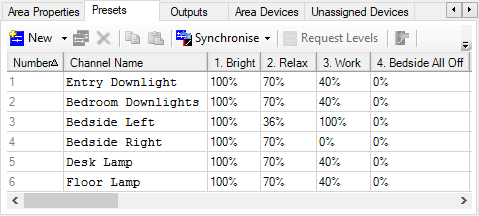
Interact Hospitality default scenes are Bright, Relax, Work, Bedside Off, and Entry Off. Presets are offset by 8 at sunset and returned to normal at sunrise.
Other scenes can be prepared to suit the exact requirements of the lighting designer. For example:
-
Welcome scene - light intensity based on time of day with curtains open and the TV showing a welcome message can help new guests explore their room.
-
Turndown scene - In the evening after turndown, the room can be dimmed with a soft focus on the bed and pillow gifts (Turndown scene can only be activated by staff)
-
TV/Movie scene - A guest can choose a scene tailored for enjoying TV and films with softer lighting and no glare, such as bedside or table lamps only.
-
Reading scene - For guests wanting to sit in the reading chair or for brighter task lighting on the desk.
Scenes can also be dynamic, taking into account natural daylight or time of day, in achieving your intended effect. Rather than having multiple buttons for the same area to recall different lighting scenes – for example in the bedroom, Morning, Afternoon, Evening and Night scenes can be recalled by a single button on a user interface programmed so that the right scene is recalled for that specific time of day. This allows for a simplified experience with fewer buttons required. Examples of this logic can also be found in bathrooms to allow a softer light level upon entry during the night, instead of traditional controls which would just turn the lighting on to 100%. The options of adaptive configurations are only limited by the imagination.
Colorful scenes
Tunable white and color control can be offered with DALI luminaires or DMX luminaires. DMX offers full color control using Red, Green, and Blue channels. The DDRC-GRMS-E can control up to 64 DMX channels.
|
Suggested color temperatures for tunable white scenes:
|
Tunable white offers additional vitality scenes. The following four scenes use (proprietary) scientifically tested combinations of color temperature and lighting intensity:
-
Standard - Cooler tones at higher intensities for more functional activities.
-
Creativity - Warm, dimmed lighting supports creativity and cooperation.
-
Focus - Bright light supports focus and concentration.
-
Presentation - Warmer tones at lower intensities for more emotional activities.
Configuring HVAC
HVAC control has the potential for the most energy savings in the room. In some climates, HVAC can consume as much as 60% of the energy in guestrooms. Integrating control of this service is therefore a significant opportunity to drive efficiency.
Every Antumbra user interface includes a temperature sensor, allowing you to choose the most representative location from which to measure current temperature and trigger heating or cooling. This could be time based - measuring from the entrance in the daytime and switching to readings from the bedside overnight to most accurately reflect guest behaviors. Alternatively, you can choose average readings from different groups of sensors (multi-temperature aggregation) for an accurate overall representation of the guestroom.
| Additionally, the humidity sensor is regularly polled by a task in the room controller to display the value on the dashboard. |
Guests are offered manual control of HVAC features such as fan speed and setpoint (only setpoint is shown, not current temperature). HVAC can be automatically shut down or set to a different setpoint when the room is checked-in/out and/or occupied/unoccupied.

Across the world different regions cool and heat their spaces to seasonal setpoints, nominally set as summer minimum and winter maximum levels. The global areas in the system are used to communicate day/night and seasonal changes.
Research suggests that for every 1°C reduction in heating/cooling, up to 10% energy savings can be achieved. To help you achieve this, HVAC integration enables you to present your guests with the choice to activate Green Mode as part of your brand’s sustainability messaging.
-
Switch to Green Mode through a simple leaf icon on the AntumbraDisplay. This activates a wider setpoint tolerance of 2-3°C (or your choice of setpoint) to save energy and allow guests to engage with making a difference in energy consumption.
-
Not take part, and instead set their temperature preferences which the system maintains (default).
| For more information, refer to the Fan Coil Unit Controller Commissioning Guide. For system-level HVAC integration, refer to CoolAutomation Integration. |
Multi-temperature aggregation
By reading a combination of different temperature sensors at different times of the day, multi-temperature aggregation provides a more meaningful temperature for an area, considering temperature gradients and intended usage.
The DDRC-GRMS-E polls individual sensors using DyNet2 physical messages for their actual temperature reading. These values are assigned a configurable weight% then averaged to create the aggregated temperature value. Then an aggregated temperature message can be sent from the HVAC area.
A logical message to change the active mode determines which group of sensors to read. For example, 1C,02,24,48,00,01,FF (Active mode 1), 1C,02,24,48,00,02,FF (Active mode 2).
There are typically two active modes:
-
Daytime - The average of temperatures from multiple sensor readings is made and provided to the room network for the HVAC controller (e.g. FCUC/CoolMaster/BACnet) to use for heating/ cooling. This enables a truly representative room temperature enhancing energy efficiency (not over heating/cooling) and maximizing guest comfort.
-
Overnight - Only selected (bedside left and right) sensor readings are taken to represent the guest’s location in the space, further enhancing guest comfort.
Configure multi-temperature aggregation
-
Select the room controller.
-
Add the Antumbra panels to the room controller.
-
Click the Temperature tab.
-
Set the applicable properties. Refer to the Temperature editor properties table below.
-
Click
 Add Group.
 -
Enter a Name for the temperature group.
-
Enter the group’s Active mode number.
-
Select a Logical area, Join, and BLA, if applicable. The logical area is set to the default HVAC area 17.
This is the area that sends the aggregated temperature message to the trunk network. The BLA is set to default dummy HVAC area 217 (This area does not need to exist in the project and is used only within the room by the DDRC-GRMS-E and FCUC tasking).
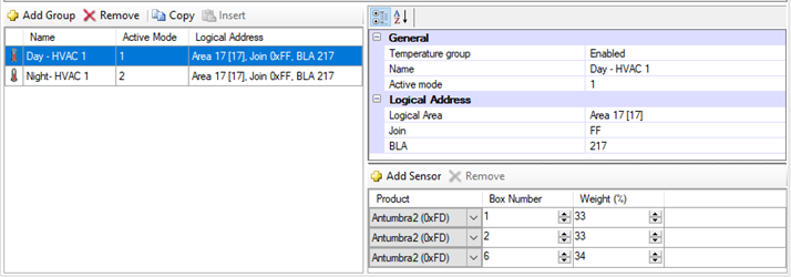
-
Click
Add Sensor for each Antumbra that you want in the temperature group (up to eight). -
Enter the Antumbra Box number.
-
Enter the Antumbra temperature reading Weight % (total must add up to 100%).
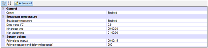
Temperature editor properties
General
| Property | Description |
|---|---|
Control |
Enabled or disabled. Used to enable/disable the multi-temperature aggregation feature. |
Broadcast temperature
| Property | Description |
|---|---|
Broadcast temperature |
Enabled or disabled. When enabled, sends the aggregated temperature message. |
Delta value (°C) |
The minimum temperature change required to trigger an aggregated temperature message. |
Min trigger time |
The minimum time that must elapse to trigger an aggregated temperature message. |
Max trigger time |
The maximum time to trigger an aggregated temperature message. |
Temperature group properties
General
| Property | Description |
|---|---|
Temperature group |
Enabled or disabled. Used to enable/disable the temperature group. |
Name |
Temperature group name. |
Active mode |
Index number to set the active temperature group. This is sent via a DyNet1 User Preference message. Up to 16 temperature groups are supported. |
Logical Address
| Property | Description |
|---|---|
Logical Area |
Enabled or disabled. |
Join |
The static join of the device. |
BLA |
Base Link Area. A dummy HVAC area. Messages to this area stay within the room and are not sent to the trunk. |
| For consistency of operation, you should still use the temperature aggregation feature even if you are only taking readings from a single sensor. |
| If not using temperature aggregation at least one Antumbra should be configured to broadcast temperature to the HVAC area. (17, 18, or 19). |
HVAC for large suites
The DDRC-GRMS-E tasking template library provides for up to three HVAC areas (17, 18, 19). A thermostat (AntumbraDisplay) is required in each area to measure the actual temperature and allow the user to adjust the setpoint.
In the library there is also an HVAC task placed in the DDFCUC (or Antumbra UI if not using the DDFCUC for HVAC) to enable additional HVAC areas for large suites and public spaces. A copy of the HVAC task is required for each additional HVAC area.
-
In DDRC-GRMS-E > Tasks > Activate Feature settings, set the Large Suite property to True.
-
If required, in the Routing editor enter a number (larger than 20) in the Area offset multiplier and the Box number multiplier properties to cater for the additional HVAC areas.
-
In the Areas tree, copy and paste one of the HVAC areas to create an additional HVAC area. For example, area 20, 21, 22, 23, etc. If using a DDFCUC in the room, you also need to copy and paste one of the Room Only HVAC areas to create an additional matching FCUC HVAC area in the 200 range, e.g. 220, 221, 222, 223, etc.
-
In area 3, create an additional logical channel for each HVAC area that has a Balcony/Window switch. This enables the Energy Holdoff signal to turn the air conditioning on and off (according to the HVAC Off Delay and HVAC On Delay) when the balcony door/window is opened/closed.
-
In DDFCUC > Tasks > Activate Feature settings, set HVAC Object, FCUC Conversion, and Balcony/Window (if applicable) to True.
-
In DDFCUC > Tasks > Task Controls settings, enter a unique Offset Delay and Message Delay so responses to HVAC events in different areas do not all happen at the same time (to reduce network burden).
-
In DDFCUC > Tasks > Areas settings, click the GRMS Template HVAC Area > Change button and select the new HVAC area number. Also, click the FCUC HVAC Area > Change button and select the new matching area number from the 200 range.
-
Configure the HVAC Controls properties, including the Balcony channel number if applicable.
-
Click
Save to Device.
| In the Room Mapping table, ensure that the Room Area Offset has a large enough range to allow for additional HVAC areas. |
| If using VRF/Split Units or another HVAC system (not the DDFCUC) then add a DACM with the HVAC task to your job. |
Configuring network user interfaces
Controlling the lighting in the room, by switching, dimming, or adjusting the color of areas and channels, is the key to helping guests feel comfortable during their stay.
Rather than large banks of switches and confusing settings, the system can present your guests with intuitive, logical groupings of buttons with appropriate names and/or icons. Simplifying usage to an effortless button press encourages adoption and use of the system by people regardless of their technological comfort level.
Using a network user interface allows the user to interact with the system more intuitively to control different system functions. The built-in button indicators or display can give the user feedback on the current system status.
Inputs from network user interfaces are triggered by a button press from the user. The inputs are configured in the Buttons Editor for each user interface. Additionally, the AntumbraDisplay Display and Buttons Editor allows you to select icons and text for room information and functions on the display.
For room status indicators, instead of using lighting channels you can use a network user interface or third-party panel outside of the room to indicate Do Not Disturb/Make Up Room/Laundry Pick Up/Service Pickup.
This user interface may also include a doorbell function that can flash the lights or ring the doorbell when paired with a third-party door chime. Indicators can be set/cleared from the main button user interface inside the room and/or from an integrated room booking system.
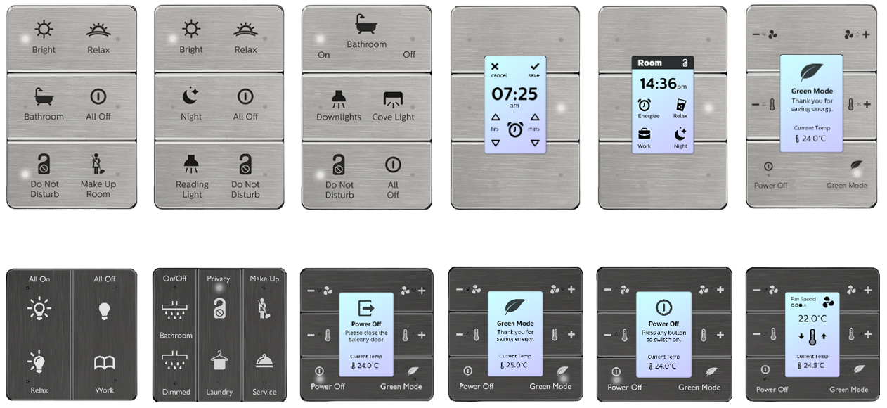
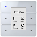
Network user interfaces may include AntumbraButton, AntumbraTouch, AntumbraDisplay, or Revolution.
| On each panel, the location of the Goodnight button should be closest to the bed. |
Room status buttons
Room status information is controlled by the Room Status function. This is displayed on the dashboard and sent to the property management system (PMS). These functions can be assigned to the dry contact input switches on the DDRC-GRMS-E or DLLI8I8O, or to any button on an Antumbra interface.
| These functions are already programmed in the STR Template Library to control room status information. |
Room Status Function
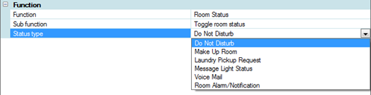
The Toggle room status sub function uses a single button to turn a status on and off. Click the Status Type dropdown list to select a status.
The Set room status sub function uses a single button to set a status value on (Set) or off (Reset). Click the Status Type dropdown list to select a status.
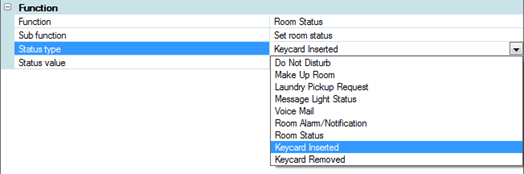
The Status value for sub functions Keycard Inserted (occupied) and Keycard Removed (unoccupied) is Set.
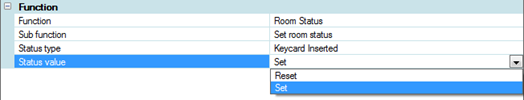
The Status values for the sub function Room Status are:
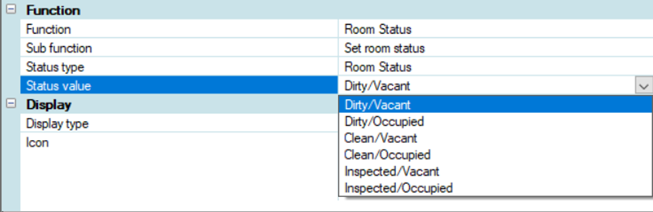
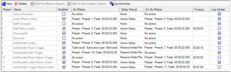
Antumbra preconfigurations
The Dynalite Application Communication Module (DACM) can store multiple configurations in a single unit.
The installer can then select a configuration by setting the DIP switches on the DACM, with no further commissioning. This allows all Antumbras to perform the functions of the other Antumbras in the room based on the DIP switch setting, for example, Entry, Bathroom, Bedside left, Bedside right, Living Room, Desk, etc.
| The number of configurations is limited by the EEPROM size. AntumbraDisplay consumes more space due to graphical elements. Ideally all configurations would be on a single DACM, but you can split the multiconfigurations for your project across two or more DACMs if required. |
-
Starting with an SB job containing all the required Antumbra configurations, either:
-
Click
 Insert Device from List (or Ctrl+D) to create an Antumbra Multi-Configuration device.
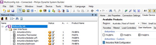
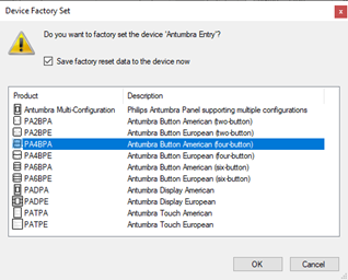
-
Right-click and
 Factory Set a compatible Antumbra device on the network to Multi-Configuration.
-
-
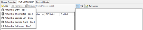
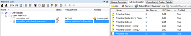
In the Multi-Configuration Editor tab, use the
Add button to add any of the Antumbra devices in the job.
-
Set the required properties for each of the devices.
-
Click
Save To Device to save to the Multi-Configuration device.
Note that if the DIP switches on the device are set to the value of any of your configurations, the device will restart with that configuration immediately after saving.
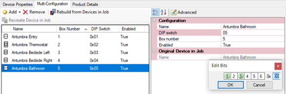
Antumbra Multi-Configuration Properties
| Property | Description |
|---|---|
Name |
This is the name of the configuration. It defaults to the same name as the original device in the job, but it can be changed. |
DIP switch |
This sets the DIP switch value (0 – 63) for the selected configuration. It’s recommended not to use 0, and to set the DIP switches on the actual device to 0 while commissioning. |
Box number |
This is the spur box number that the device will have when the configuration is recalled. It defaults to the same box number as the original device in the job, but it can be changed. Note that you can create multiple configurations with the same box number. In the picture below there are 2 devices called Antumbra Kitchen with box number 84. This may be useful for quick configuration changes onsite. |
Enabled |
True or False |
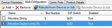
Synchronizing configuration updates from original devices
Click the ![]() Rebuild from Devices in Job button to synchronize the current settings of all the original devices in the job to the Multi-Configuration device.
Rebuild from Devices in Job button to synchronize the current settings of all the original devices in the job to the Multi-Configuration device.
Loading a multi-configuration device from the network or from a hex file
If a multi-configuration device must be loaded from the network or from a hex file, the original devices will not be known. In this case the configurations each appear with a ![]() icon beside them. The Original Device in Job > Name field will also be empty.
icon beside them. The Original Device in Job > Name field will also be empty.
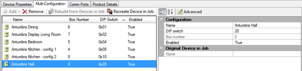
For devices in this state it is possible to change the name, DIP switch, and Enabled settings, but not possible to change the box number.
To change the box number or any other device configuration, selectthe config you wish to edit then use the ![]() Recreate Device in Job. The image below shows a recreated device. Note that devices are recreated in the job without a box number.
Recreate Device in Job. The image below shows a recreated device. Note that devices are recreated in the job without a box number.
Now that the Antumbra Hall device exists in the job, you can change its configuration and then sync it back to the Multi-Configuration device using ![]() Rebuild from Devices in Job.
Rebuild from Devices in Job.
Configuring third-party user interfaces
Dry Contact Inputs
In addition to a network sensor or user interface, room functions can also be triggered either from an AntumbraLite button panel or a third-party interface (such as a button panel or a window/door reed switch.)
Inputs are provided by a dry contact input on a network device such as the DDRC-GRMS-E controller or a DLLI8I8O dry contact interface device. This allows the control system to detect button presses or door open/close state. Dry contact inputs also enable the use of custom manufactured user interface panels that match the project’s design requirements.
A third-party interface may be one of the following:
-
A user interface button with or without LED indicators.
-
An output from another system.
-
An open/close switch on a keycard holder, window, or door.
|
Additionally, you can configure the DDRC-GRMS-E UL924 input to trigger an emergency preset via the Device Properties Editor. UL924 input is different to a DyNet panic message. There is no network message, and it is not reversible via DyNet packets. |
Card Drop Integration
-
In System view, select the DDRC-GRMS-E and open the Tasks tab.
-
Click
 Edit to open the Tasks Editor.
 -
Click the Persistent Memory tab.
-
Set persistent memory index 10 $Card_Drop to 01.
-
Close the Task Editor and click to save changes to the job file.
-
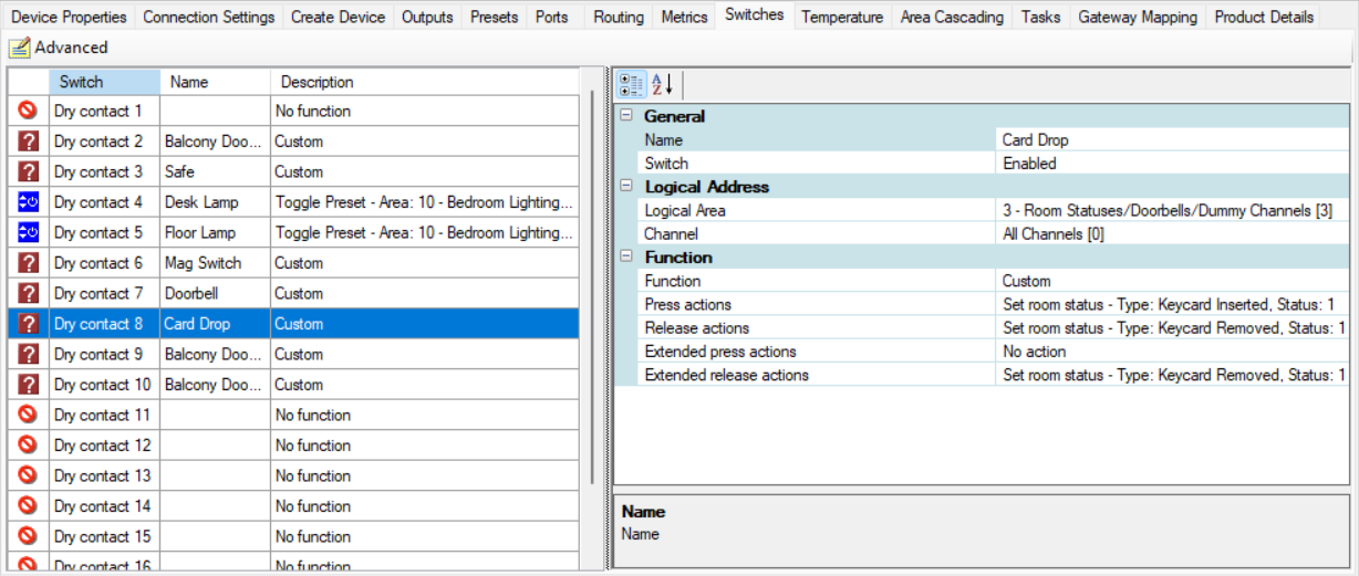
Select the Switches tab
-
Configure Dry Contact 8 (Card Drop) to send the Set room status - Keycard Inserted/Removed messages. When the card is removed the system marks the room as unoccupied and disables all keypads and dry contacts until reinserted.
-
Click
Save to Device. -
Click File >
 Save to save the job.
DLLI8I8O Dry Contact Inputs
A DLLI8I8O dry contact interface with LED indicators for each button gives the user feedback on the current system status. The indicators can show which button has been pressed or which mode is selected. The inputs are configured in the Switches Editor for the device.
Buttons connected to panels can perform identical functions by configuring the inputs accordingly, or by wiring the inputs in parallel.
Other Third-Party Inputs
Other third-party devices with RS-232 or RS-485 ports connect to the control network via an integration device. This method is commonly used for:
-
AV systems with built-in DyNet compatibility, such as AMX and Crestron.
-
Third-party control of the lighting system.
-
Lighting system status feedback to a third-party system.
-
Notification of alarm conditions, such as circuit breaker trips and smoke or gas detection.
Configuring Third-Party Sensors
DDRC-GRMS-E dry contact inputs 1 to 4 can be connected to a third-party sensor for occupancy control. Occupancy is checked 30 seconds after the magnetic switch input detects that the front door has been opened and closed.
-
In System View, select the DDRC-GRMS-E Tasks tab.
-
Set Activate Feature > Dry Contact Sensors to True.
-
Set the Sensor Controls > Sensor Timeout Delay to the required timeout period. The delay must be longer than the sensor’s internal timeout period.
-
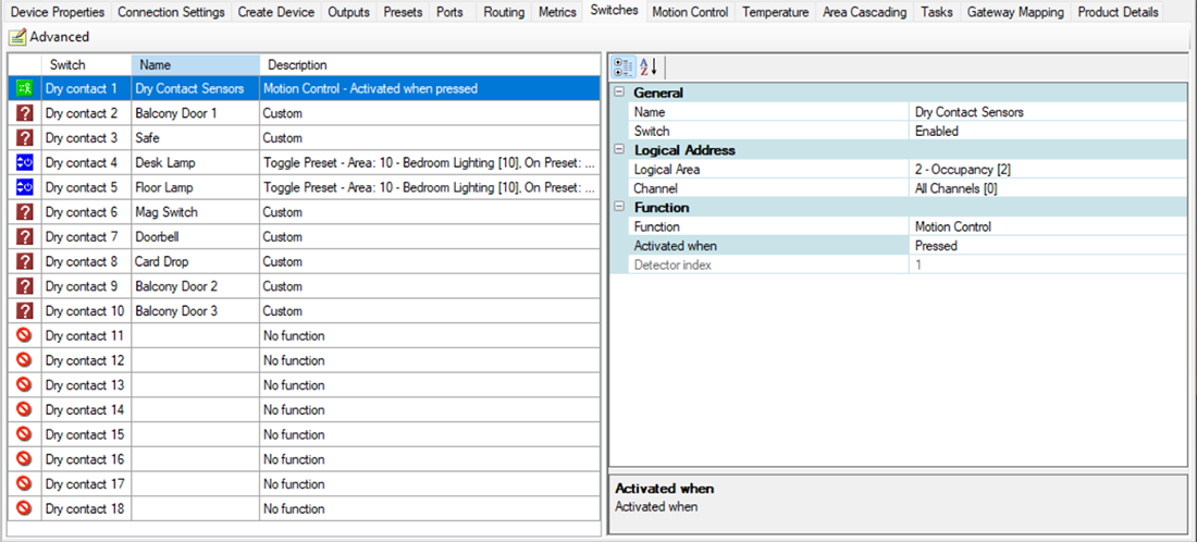
Open the Switches tab and configure one of the first four switches to Logical Area: 2, Function: Motion Control.
-
Open the Motion Control tab and tick the Enable Motion Control checkbox for the respective input (1 to 4) connected to the third-party sensor. There is no need to change the motion control properties as they are already configured by the task template.
-
Click
Save to Device. -
Click
File Save to save the job.
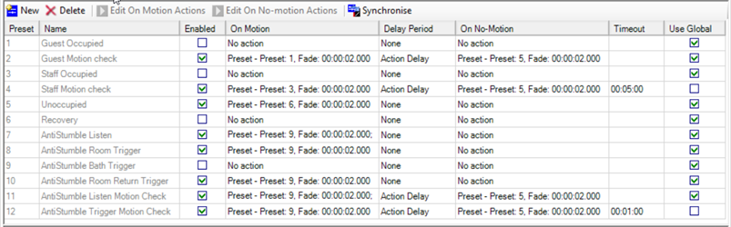
Configuring Wake-Up
The Wake-Up feature mimics sunrise by simulating the dawn light before a set wake time. Wake-up lighting can reduce sleep inertia and improve well-being.
Wake-Up is configured using a combination of devices and software:
-
AntumbraDisplay (contains the wake-up tasking)
-
Multiroom Dashboard
-
PMS (optional)
-
Ethernet gateway (if using Day Rhythm feature)
-
Controller with dimmable and color control outputs
-
Tunable white drivers and lamps
| If wake-up is used, the Activate Feature section of the DDRC-GRMS-E STR Template Library must be set to True so that the alarms get cleared on check-out. |
The wake-up alarm can be set from the AntumbraDisplay, the Dashboard, or the PMS. The alarm time is saved in the AntumbraDisplay, which shows the alarm time and listens for time messages from the real-time clock in the PDEG/PDDEG-S.
Depending on the specific configuration, sometime before the alarm triggers (default = 20 minutes), a task typically recalls a sequence of presets for both the main lighting area (10) and the spare colored lighting area (12). It also changes the page on the AntumbraDisplay to the snooze page where the guest can choose to:
-
Let the sequence continue
-
Turn it off and turn the lights on to bright
-
Turn it off and turn the lights off
-
Snooze for 9 minutes, turning the lights off.
After the snooze period expires, a truncated sequence resumes.
The task must be on the AntumbraDisplay, and requires area 200 for the display and wake-up opcodes for area 3 for the actual commands to communicate with the STR Template Library tasks in the DDRC-GRMS-E.
Home No Alarm
|
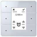
12 Hour Wake Alarm
|
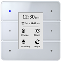
Home Alarm Set
|
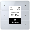
12 Hour Wake Snooze
|
If applicable, all actions can be saved and synchronized with the PMS - refer to PMS integration.
Configuring sensors
Accurate guest detection is key to allowing the status and condition of the room to be automatically updated, whether for guest comfort or operational efficiency. Through a combination of sensor hardware, integration design and contextual logic we can determine whether a room is occupied, whether they are a guest or staff, the natural light level, the current temperature, window/door status, etc.
This detection can recall either a welcome scene or intelligently remember the previous scene and revert to the guest’s preferences. Combined with access control, the room services can react differently to staff occupancy compared to guest occupancy.
In unoccupied states, such as during breakfast or in the daytime, the room can step down services over a period of time. Cutting all HVAC for example can maximize energy savings, while stepping to a 3-4°C difference allows the room to revert to its previous state more quickly than when HVAC is turned off.
There are three categories of guestroom sensors:
-
Bedroom sensors - detect where people sleep.
-
AntiStumble sensors - detect feet when they leave or enter the bed.
-
Bathroom sensors - detect anything else (bathroom, balcony, entry, closet, living room, etc.).
Bedroom sensors
Motion control detection in the bedroom sensor triggers preset scenes in the Occupancy area.
The Occupancy Area task in the STR Template Library then uses this input to update the occupancy status of the room.
AntiStumble sensors
AntiStumble sensors are placed under the bedside tables. They recall a low light level in bedside and bathroom lights to help guests navigate to the bathroom at night. The sensors are configured to detect motion only when the room is in the Goodnight preset or when the light level is below a certain value.
Nightlights can be specified in the bedroom and bathroom to use movement detection from the bedside (wall) sensors and bathroom (ceiling) sensors whenever the Goodnight preset is active.
The sensor timeouts should allow sufficient time to navigate from the bedside sensor detection zone to the bathroom sensor detection zone. When a guest returns to bed, the nightlights automatically switch off, based on the timeout since last movement was detected (default timeout = 30 seconds after leaving the bed and 3 seconds after returning to bed).
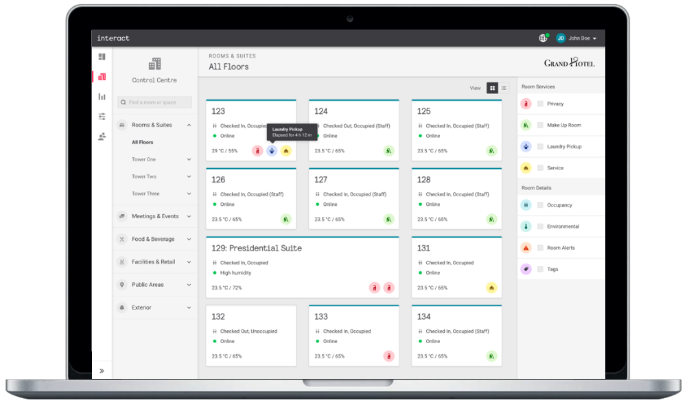
Configuring room monitoring
Room monitoring can be performed by the corridor panel and/or the room monitoring software.
-
The corridor indicator panel outside of the room can signal the DND/MUR/LPU/RSP or occupancy status of the guestroom to hotel staff.
-
The DND/MUR/LPU/RSP function requires a DLLI8I8O or room controller digital output to drive the indicators and a button panel within the room for the guest to set their room status preference.
Networked rooms provide many benefits including automatic reporting of the room status to the central System Manager Server. When rooms are monitored, additional system messages are also captured, such as preset state, channel levels, and DND/MUR/LPU/RSP status.
With the Multiroom Dashboard installed, operational staff can monitor the status of all guestrooms and are automatically informed if the system detects a fault within the network. If DALI Addressable fittings are used, then driver and lamp failure detection is also possible. System Manager seamlessly integrates with many different systems, with the Hotel Integration API enabling a wide variety of applications.
Before testing each feature, save the configuration to each device in your mockup room:
-
Select each device in the job.
-
Click
Save to Device. -
Click
File Save to save the job.
Mockup room testing
Perform scenario-based testing to confirm that all room controls are functioning according to the System Control Requirements.
Example System Control Requirements
-
Ability to control all lights in Guestroom.
-
Ability to control A/C set point temperature through a fully modulating valve.
-
Ability to control A/C Fan Coil Unit fan speed.
-
Ability to control power supply to TV.
-
Ability to control motorized curtains.
-
Ability to differentiate between guest key opening door and staff key opening door.
-
Ability to change timings as to when system takes control after guest leaves room (during the guest stay or upon checkout).
-
Ability for system to detect presence in the room, method of detection to be advised (sensor, key drop).
-
Ability to generate energy usage reports and view on lighting dashboard.
-
System must be able to determine the difference between a guest or employee entering the room to determine access to equipment.
-
System must allow an administrator to adjust/customize settings if local environmental conditions demand.
-
Equipment always powered on:
-
Mini Bar
-
Electrical outlet at desk
-
Electrical outlet in guest safe
-
Universal power sockets
-
USB Chargers
-
Example Scenario 1 – Room unoccupied
-
Dependent on the ambient temperature the system will hold the room at a predetermined temperature, this temperature should be adjustable by the system administrator.
-
FCU fan speed will be controlled to maintain predetermined temperature.
-
All lights in bedroom and bathroom will be off.
-
If there are motorized curtains, then the curtains will be closed to minimize solar gain.
-
Power to TV will be turned off.
Example Scenario 2 – Room unoccupied – employee enters room
-
System to identify that it is an employee in the room via occupancy sensor and access control system.
-
System to maintain control of A/C and predetermined temperature.
-
All lights to be powered for staff member to check they are working.
-
TV to be powered to all staff members to check signal.
-
Curtains to open.
-
System to take control of room after 5 minutes (based on operational needs) after the staff member leaves the room and return room to unoccupied status and predetermined settings.
Example Scenario 3 – Room unoccupied then guest checks in (Checked-in, Occupied)
-
When a check-in event is received the room state changes from Checked Out, Unoccupied to Checked In, Unoccupied and some settings change like GPO on, Temp Setpoint change.
-
When a guest enters the room the room state changes to Checked In, Occupied mode that changes more settings including lights, curtains and temp setpoint (day/night dependent).
-
When the guest opens the door for the first time, the room should go into a welcome scene, this welcome scene should include specific lights.
-
System signals the controls to adjust the A/C to 23°C (based on operations requirement).
-
System signals the controls to switch on TV.
-
Systems signals the control to open the curtains during daytime or close them in the evening unless we want to highlight the view.
Example Scenario 4 – Guest is checked into room but leaves the room
-
Room goes to Vacant state 15 minutes (based on operations requirement) after the guest leaves the room.
-
Dependent on the ambient temperature the system will raise the room to a predetermined temperature, this temperature should be adjustable by the system administrator.
-
FCU fan speed will be controlled to maintain predetermined temperature.
-
All lights in bedroom and bathroom will be off.
-
If there are motorized curtains, then the curtains will be closed to minimize solar gain.
-
Power to TV will be turned off.
Example Scenario 5 – Guest is checked into room but leaves the room then returns to room
-
The system should identify the guest as opposed to a staff member.
-
The AC should work to restore previous guest preference temperature.
-
If there are motorized curtain closers, then the curtains/blinds should open during daylight.
-
During daylight no lights should come on until the guest switches a light on.
-
After dark, then the welcome scene at the time of arrival should come on.
-
TV should not come on until guest switches it on.
Example Reports for Hotel Staff
-
Access available for housekeeping to determine vacant room for cleaning via mobile app.
-
Access available for housekeeping to determine occupied room but no guests inside for daily cleaning and room make up/turndown.
-
Access for Housekeeping & Engineering to identify which rooms housekeeping staff are in, (this can be timed based on hotel operations requirement).
-
Access available for engineering department to determine all the same items as housekeeping
-
plus functionality of MEP systems:
-
Lighting - (including individual lamp failure identification if smart LED lamps are installed)
-
Room temperature
-
Room humidity
-
FCU valve position
-
Chilled water/heated water temperature
-
Fan speed
-
Curtain position
-
Electrical Meter reading kWh
-
-
plus Links (interface with Computer Aided Facilities Management system). This can be multi-functional - alerts on controlled modules, maintenance history (e.g. get information on last service visit or complaint about a specific room, time, and damaged / repaired item).
-
-
User dashboard session access.
-
Customizable dashboards and easily accessible to the hotel management / staff.
-
An optional mobile app could easily be downloaded and used to control A/C and Lighting.
-
DND, MUR, Bell module must have the ability to detect guest presence before staff push the bell.
-
Capture guest preferences such as temp, energy consumed, reported issues, number of stays, etc.
Test luminaire interoperability
The System Engineer tests all room lighting functions to ensure correct switching, dimming, and color control of luminaires.
If there are issues these must be addressed or accepted by the customer. You must obtain customer signoff to complete this step.
| The Multiroom system supports all open standard dimming methods, providing smooth, flicker free dimming. For complete assurance, pair with Philips Lighting fixtures and drivers. |