RS-485 Bridge
Trunk and Spur
Trunk-and-spur topology is used to scale the system so that a project can be broken down into subnetworks. Trunk communication to each DDNG485 uses the high-speed DyNet2 protocol, which supports an extended addressing and opcode set. Each DDNG485 then communicates to the devices on its spur/subnetwork usings the lower-speed DyNet1 protocol.
One of SB’s notable features is that it supports the merging of separate job files. This enables multiple commissioning engineers to work on separate parts of the system in parallel, drastically speeding up the creation of complex projects at scale.
Large projects that use an RS-485 trunk-and-spur topology will have a minimum of two job files:
-
A 'trunk and network bridges' job file
-
One or more 'spur and specified devices' job files
As each spur is commissioned, the spur job is imported into the trunk job under a DDNG485 (in System View).
For smaller projects with only a single job file, devices can be inserted under a DDNG485 (in System View) to create a spur.

| Some projects may require multiple trunk networks such as an Ethernet trunk connected to an Ethernet gateway, connected via an RS-485 (DyNet2) trunk to a DDNG485, which is then connected via RS-485 (DyNet1) to spur devices. |
SB includes the following editors for the DDNG485:
-
Device Properties
-
Connection Settings
-
Create Device
-
Bridge Address Ranges
-
Ports
-
Routing
-
Switches
-
Metrics
-
Area Cascading (Technician license only)
-
Tasks
-
Product Details
Address Offsets
In multistorey buildings, each network bridge/gateway is configured with an address offset for its spur (physical and logical address range, e.g.: 1000, 2000, 3000, etc.). Logical address offsets in each bridge enable reuse of area numbers (and use of common area numbers when required).
Routing by the bridge ensures that only systemwide and inter-spur communications are sent over the trunk. Intra-spur communications remain within the spur subnetwork.
The diagram below shows different logical address range offsets on two spurs and a common logical address range shared by both spurs. A common logical range is often added to other bridges (Areas 201–255 in this example) for logical messages to other floors.
Physical address offsets in each bridge enable it to maintain electrical isolation from the trunk and allow the reuse of device box numbers on spurs with different offsets. The diagram below shows different physical address range offsets on two spurs and a common physical address range when using two bridges as a single spur.
|
A common logical range enables the system to address areas that span multiple spurs. A common physical range enables devices to appear on a single spur when attached to different bridges. |
Bridge Configuration Wizard
The Bridge Configuration Wizard provides a quick way to configure the DDNG484 as a trunk-and-spur bridge. Ensure that you always run the wizard first before making any manual adjustments to routing or filtering with the Routing editor.
-
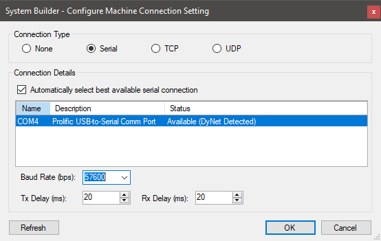
Connect SB to the network via a serial RS-485 connection.
-
Right-click the DDNG485 in the System view device tree and select
 Bridge Configuration Wizard… ( Alt+W ).
 -
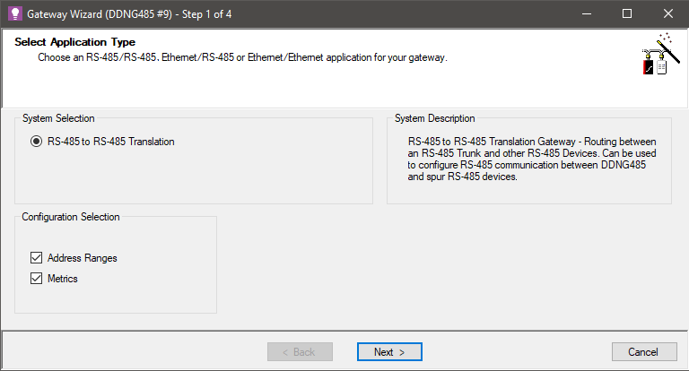
Select RS-485 to RS-485 Translation Gateway and click the button.

-
Click
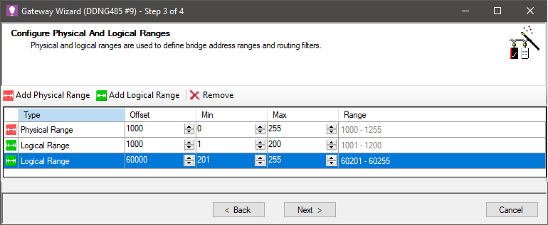
 Add Physical Range and enter Offset, Min and Max values.
 -
Click
 Add Logical Range and enter Offset, Min and Max values. Primary address Min value must be 1 or 0 (see Note).
 -
Click
 Add Logical Range again (optional) to enter address ranges that are common to multiple bridges. The range defined by the Min and Max values must not overlap with the other logical ranges. Click the button.
Do not use common areas unless you have a genuine need to control areas on different floors from a user interface/sensor on another floor. The primary logical range for the spur can be changed to start from 0 if you want to allow Area 0 (All Areas) messages to be sent from the trunk. You must enable the Area Zero Transmit property on the port record for the bridge. Spur devices may require further configuration to support this. -
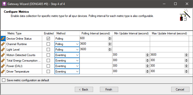
To enable metrics, tick the corresponding checkboxes and enter a Polling Interval as required. Click the button
To minimise network traffic, ensure that only necessary metrics are enabled. 
-
Click
 Save to Device ( F12 ).
 -
Repeat this procedure for every bridge in your system.
-
When complete, click File >
 Save ( Ctrl+S ) to save the job to your PC.
High-Speed Trunk
The default DyNet1 and DyNet2 baud rate is 9600. You can increase this to 57600bps on an RS-485 trunk connection to enable communication with multiple RS-485 spurs.
| When saving to the device after configuring a high-speed trunk on Port 2 of the DDNG485, SB will lose connectivity if connected to Port 2. To maintain connectivity, you can either connect SB to Port 1 (spur), or configure SB to connect to the trunk at the speed configured for Port 2. |
-
Connect via a serial connection to the spur (Port 1).
-
Select the DDNG485 in System view and Open the Ports editor.
-
Select
 Comm Port 2.
 -
Set the Port type to DyNet2.
-
Set the Baudrate to 57600.
-
Click
 Save to Device ( F12 ).
| DyNet over RS-485 can be configured up to a maximum of 115200bps with a 120 Ω end-of-line resistor installed across the D+ and D- terminals on the first and last device to prevent network reflections. |
-
Select the EG in System view and open the Ports editor.
-
In the lower window, select
 Comm Port 1
 -
Set the Port type to DyNet2.
-
Set the Baudrate to 57600.
-
Click
 Save to Device ( F12 ).
You can now reconnect SB to the trunk at 57600bps.
