DDFCUC
The DDFCUC is a mains powered fan coil unit (FCU) controller designed for direct connection to components commonly found in Heating, Ventilation, and Air Conditioning (HVAC) plants with FCUs.
The DDFCUC has two sets of control outputs:
-
Triac (Valve) outputs control valves and relays used for switching FCU fans and auxiliary heaters.
-
0-10V outputs control valves and fans with analog inputs.
There are four configurable control inputs to interface with dry contact outputs, 0-10VDC outputs, and a 20 kΩ NTC temperature sensor.
To facilitate the use of a single platform for all electrical services, the controller integrates local HVAC control with DyNet over RS-485, enabling interaction with the entire control network.
| Always connect Valve 1 to HOT water and Valve 2 to COLD water. |
| The controller can also use data from networked temperature sensors, such as those embedded in the PDTS, Antumbra, and Revolution user interfaces. |
FCU Operation
An FCU typically includes a single fan and one or more heat-exchanging coils with control valves feeding hot or cold water.
The DDFCUC compares the measured room temperature against a setpoint value and adjusts the thermal output of the FCU by varying the fan speed and hot/cold water flow to achieve the setpoint value.
To enable HVAC control, the controller requires the following information about the plant.
-
Valve configuration
-
Fan configuration
-
GPR (heater switch) load specification
-
Input/fault signals
-
Temperature sensor data
| Third-party device specifications are required for configuration. |
|
When selecting the DDFCUC output configuration, ensure that the required voltage, current, and lifetime expectancy requirements of both the controller and the FCU are met. For example, a triac output can operate a valve drive for an almost infinite number of cycles, but valve wear increases with more frequent movement. Relay outputs also have a limited number of operating cycles depending on the load and the relay’s mechanical construction. |
Plant Structure
The controller can be connected to valves, an electric heater, and fans in an FCU, as well as a temperature sensor and other sensors.
-
Valves control the flow of hot and cold water through a heat exchanger. For electromotive (floating or staged) valves, the valve position is set by travel time. For 0-10V modulating analog valves, the valve position is set proportionally according to the applied voltage.
-
The General Purpose Relay (GPR) may be used for several applications but typically controls a contactor for switching an auxiliary electric heater.
-
A fan driven by an electric motor changes the air speed to blow air past the heat exchanger and through a filter into the room. The air is heated or cooled at the heat exchanger, bringing the room to the required temperature setpoint.
Typically, the condensed water generated by the cooling process is collected in a drip tray and piped out to a drain.
| To save energy, simultaneous active heating and active cooling is disabled by default. |
FCUC Systems
An FCU can be designed as a 4-pipe, 3-pipe, or 2-pipe system.
-
In the 4-pipe system, separate water circulation loops are used for hot and cold water. This system requires two separate heat exchangers for heating and cooling, each controlled by a valve.
-
The 3-pipe system is similar to the 4-pipe system, but uses a common return flow for hot and cold water.
-
The 2-pipe system uses a single water circulation loop to either heat or cool the room. This type of FCU has only one heat exchanger and one valve.
Many HVAC systems use a 2-pipe FCU for cooling only, with heating functionality provided by an auxiliary electric heater controlled by the GPR output connected to a contactor.
|
The DDFCUC only supports non-seasonal 2-pipe systems that are fixed to either hot or cold. Seasonal systems that change from heating to cooling depending on the time of year are not supported |
Fan Drives
The DDFCUC can control the following fan types:
-
1-3 speed fans are controlled via the FAN-LOW/MED/HIGH relay outputs. The fan is supplied from AC mains via a 10 A max rated fuse or circuit breaker.
-
0-10V controlled fans are connected to the 0-10V FAN and COMMON outputs. The fan power supply comes from a suitable Vaux source, typically 24 V AC/DC.
1-3 speed fan
|
0-10V fan
|
Valve Drives
The DDFCUC controls electromotive valve drives that use a small electric motor to open and close valves. These drives are one of two types:
-
Electromotive raise/lower (travel time) valve drives are controlled with open/close commands using the DDFCUC triac VALVE 1/2 - OPEN/CLOSE outputs. When an open/close command is applied, the valve opens/closes at a set speed determined by the mechanical construction of the valve and the drive. With no control signal applied, the valve stops and stays in the current position. The control signal is generated by a PID regulator intended to keep the valve in the position that optimally maintains the set temperature. Depending on the time period that the control signal is applied, the valve can be set to any position with a percentage value. The valve is thus regulated via the valve opening (0-100%) similar to the proportional valve drive.
-
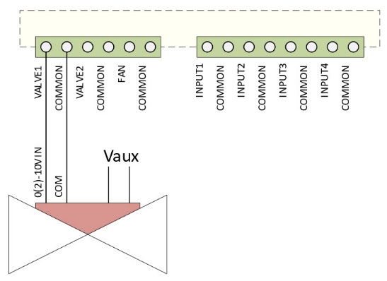
Electromotive proportional (analog) valve drives are controlled via an analog 0-10VDC signal from the DDFCUC 0-10V VALVE1 and VALVE2 outputs. The control signal is generated by a PID regulator intended to keep the valve in the position that optimally maintains the set temperature.
Raise/lower (travel time) valve drive
|

Proportional (analog) valve drive
|
Valve Control
The following features help to ensure optimal valve drive operation, reducing unnecessary wear and saving energy (See also: Configure HVAC Plant):
| Refer to the valve manufacturer’s specifications for required settings/values. |
-
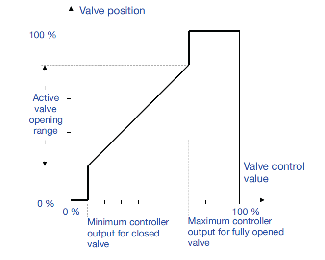
Many valves have almost no flow or cause a disruptive 'whistling' resonance when slightly open, and/or hit their maximum flow rate at only 60-80% open.
Restricting the mechanical valve operation limits with valve minimum level (%) and valve maximum level (%) can minimise these issues while also reducing wear from unnecessary movement when there is a negligible demand for heating or cooling.
-
Configuring the valve minimum control efforts (%) reduces valve wear from unnecessary micro-adjustments below this threshold. Alternatively you can leave this disabled (0%) and instead set the valve minimum travel time (seconds) to achieve a similar effect.
-
The valve minimum off time (seconds) setting can further reduce wear by moving the valve less frequently, forcing a minimum interval between consecutive adjustments.

Auxiliary Heater
The DDFCUC can drive an auxiliary electric heater via the General Purpose Relay (GPR) output, typically used with an external contactor to boost the output current. The auxiliary power source Vaux is selected as per the external contactor and GPR relay ratings.
Inputs
The four DDFCUC inputs can be configured for the following functions:
-
Dry Contact Interface:
-
Smoke detector
-
Motion detector
-
Window open/close sensor
-
Drip tray overflow
-
Dirty air filter
-
Airflow detector
-
Custom
-
-
Analog:
-
20 kΩ NTC Resistive temperature sensor
-
| The local temperature sensor can only be connected to INPUT1. |