Floor Plan Window
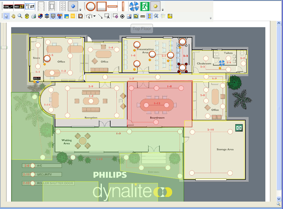
The Floor Plan Window lets you see the system layout. It enables you to place devices, fixtures, cabling, and logical regions onto a background image that represents a floor plan in your job.
To view a floor plan, open Building View and either double-click the required plan or right-click and select ![]() Show Floor Plan.
Show Floor Plan.
You can open the floor plan window at any time by selecting Window > ![]() Floor Plan Window from the toolbar.
Floor Plan Window from the toolbar.
To float the Floor Plan window, select Window > ![]() Float Floor Plan Window or press Ctrl+F9.
Float Floor Plan Window or press Ctrl+F9.
|
To open a mini map of the floor plan background image, right-click the |

Floor Plan Toolbar
-
 Pointer Mode - The pointer mode is used to select the different items on the floor plan window. It can also be used to move device and fixture icons.
 -
 Pan Mode - The Pan Mode pointer appears like a hand and is used to view the floor plan by dragging it around with the mouse.
 -
 Zoom Mode - Zoom Mode is used to zoom-in or zoom-out of a section on the floor plan. Click the Zoom Mode and select the area to magnify. The mouse wheel can also be used to zoom-in and out on the floor plan. Additionally, the slider on the Floor Plan Window can be used to zoom.
 -
 Lock Canvas - Locks all editing features so that no further changes can be made to the floor plan.
 -
 Print Current View - Prints the current view in the floor plan window.
 -
 Bookmark Current Position - The current position on the floor plan is saved. When you click Bookmark Current Position a bookmark is added under the bookmark folder in the Building View Tree. You can then name the bookmark. When a bookmark is saved the zoom level of the book-marked position is also saved.
 -
 Show/Hide Layers - Show/Hide Layers can be used to view the various layers of objects on the floor plan. You can select the Select All option from the menu to turn ON/OFF all Devices, Regions or Lines.
 -
 Display Tooltips - Enables display of tooltips when hovering the mouse pointer over items on the floor plan
 -
 Show/Hide Icon Status - Shows the current status of icons placed on the floor plan.
 -
 Highlight Area Cascading Areas - As the mouse pointer hovers over each area on the floor plan they are dynamically shaded in a contrasting color to show the Area Cascading relationships. Right-click an area to modify.
 -
 Request Levels - Displays the current active levels of the icons placed on the floor plan. You can request current levels for the selected icons or for the whole plan.
 -
 Open Shape Recognition Editor (SRE) - For vector floor plan drawings, the SRE allows you to define your fixture and device shapes and then automatically create the icons on the floor plan by searching for the shapes.
Right-click on a region to enter Edit Region Mode. In this mode, you can right-click again to access the Edit Region context menu. Right-click another part of the floor plan to exit. -
 Draw Region - When commissioning a site, a floor plan is divided into different regions. This function draws rectangular or polygonal shaped regions on the plan to represent the logical regions in the job. Double-click to complete the drawing or right-click to cancel the drawing. The following different types of regions can be drawn:
-
 Draw Area Region
 -
 Draw Base Area Region
 -
 Draw Join Region
 -
 Draw Zone Region
-
-
 Draw Line - Draw lines is used to draw a connection between devices and/or fixtures. Lines can be edited by rightclicking an existing line. The following types of lines can be drawn as straight or curved lines:
-
 Draw Fixture Group
 -
 Draw DyNet Cable
 -
 Draw DALI Cable
-
-
 Create Text - Enables you to add editable text to the floor plan. Select Create Text, drag and draw text boxes. Right-click the text box to modify.
 -
 Select fixtures to assign channel - This function shows the channel numbers for all fixtures. You can click and drag to select a group of fixtures. A dialog box allows you to assign the group to an existing channel or a new channel. Selected fixtures must all be within the same area.
-
 Create Global Coordinate - Enables you to add a reference point on the floor plan and enter the exact latitude, longitude, and altitude.
 -
 Background Image - A floor plan or reflected ceiling plan image can be inserted using the Background Image menu. You can select, replace, edit, and clear background images. Right-click on the background image to exit edit mode.
 -
 Draw Perimeter Wall - Click and drag to define the floor plan perimeter on the drawing.
 -
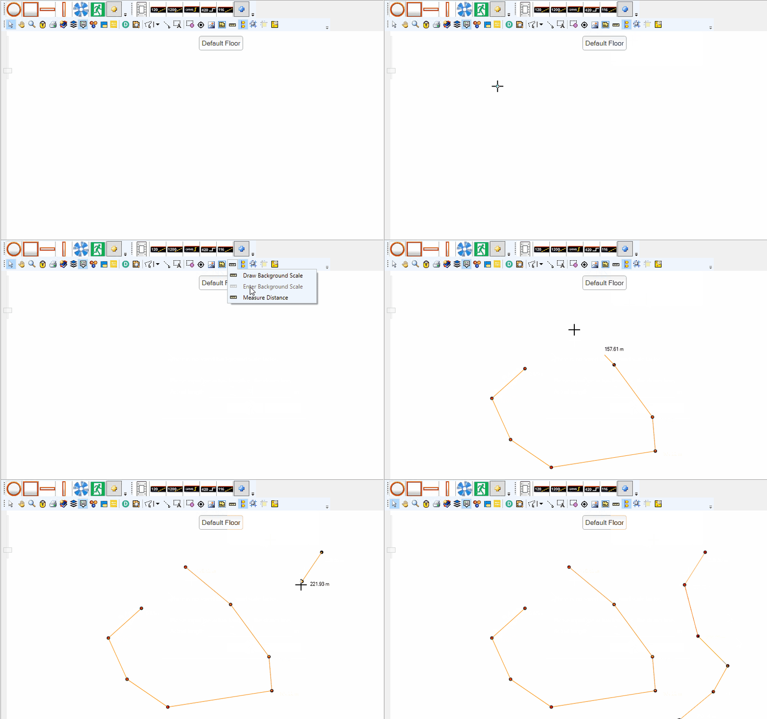
 Set Background Scale Factor - Click to Draw Background Scale (draw a line between two known points and enter the actual length to set the scale factor of the drawing). After setting the scale factor, you can also select Measure Length to check the distance between two or more points on the plan.
Tooltips can now show area dimensions and DyNet/DALI cable length. If required, you can change the ceiling height and measuring unit in Tools > Settings… > Job Settings.
-
 Smart Snap - Smart Snap is an auto alignment feature. When adding or moving icons and regions to the floor plan, smart snap will snap its alignment to the icons or regions around it. The blue lines that appear around the icon are the smart snap lines.
 -
 Show and Snap to Gridlines - Displays gridlines on the floor plan. When adding or moving icons and regions they will snap to the grid lines. The distance between grid lines can be changed in the System Builder Settings Window under the Tools menu.
 -
 Snap to Lines in Background Image - When drawing lines, they snap to lines in the background image.
Alignment Toolstrip
This toolstrip appears when two or more floor plan objects are selected. It enables flexible alignment and spacing of the selected objects. Use the tool tips to identify each alignment function.

Device Palette

Devices such as load controllers, user interfaces, sensors, timeclocks, and gateways can be easily added to the floor/ceiling plan using the Device Palette. Simply click a device on the palette then click on the floor plan to place the device. More than one device at a time can be placed on the floor plan. Right-click to exit.
You can quickly access up to six devices on the palette. To add a device, click the ![]() Add Device to Palette icon and select the device from the Create Device window. To remove a device, right-click and select
Add Device to Palette icon and select the device from the Create Device window. To remove a device, right-click and select ![]() Remove from Palette
Remove from Palette
For products with dry contact inputs, you can display the switch icons on the floor plan by dragging them from Building View. To enable switch icons, select Settings > Job Settings > Job File > Show switches in Building View, then reload the job.

Fixture Palette

Different fixtures can be easily added to the floor/ceiling plan using the Fixture Palette. Simply click a fixture on the palette then click on the floor plan to place the fixture. More than one fixture at a time can be placed on the floor plan. Right-click to exit.
You can quickly access up to six fixtures on the palette. To add a fixture, click the ![]() Add Fixture Profile to Palette icon and select the profile from the Fixture Profile Editor window. Right-click a profile to
Add Fixture Profile to Palette icon and select the profile from the Fixture Profile Editor window. Right-click a profile to ![]() Delete or
Delete or ![]() Edit it.
Edit it.
Assigning Load Control
You can assign load control by linking a fixture to a load controller output:
-
 Drag the output from the load controller onto an existing fixture icon on the plan.
OR -
 Drag the output from the load controller onto the plan to create a new fixture.
| Outputs are displayed in Building View or in the Areas View > Unassigned Devices editor. |
Fixture Current Level Indication
-
 The current light level is indicated by the color in the center of the fixture icon.
-
For standard fixtures, the color for the current level varies from dark grey (0%) to bright yellow (100%).
-
For RGB fixtures, the current color is shown.
-
For Warm White/Cool White fixtures (WWCW) a color representing the current temperature and intensity is shown.
-
-
 A blue shade indicates that the current level for the fixture is not yet known.
To poll the the current level for all (or selected) fixtures on a plan, click the ![]() Request Levels button on the floor plan toolbar.
Request Levels button on the floor plan toolbar.
To change light levels, double-click a fixture and adjust the Fixture Level slider.

Stale Icon
-
 The current level for each output is saved in the job file. As levels may have changed when the job was closed SB indicates that the levels are stale by shading the bottom corner of fixture icons with the blue unknown level color.
Multiple Fixtures to One Channel
To link multiple fixtures to a single circuit:
-
Draw a fixture group with the
 Draw Line tool
OR -
Select multiple fixtures, then right-click and select
 Group Fixtures.
If a number of fixtures are grouped into a single circuit then one of the fixtures is set as the master fixture icon.
The ![]() master fixture icon (indicated by a purple dot in the center) determines the logical configuration for the fixture group by its location.
master fixture icon (indicated by a purple dot in the center) determines the logical configuration for the fixture group by its location.
To unlink a fixture from the output, right-click the fixture and select ![]() Remove Load Control.
Remove Load Control.
A ![]() white shade indicates that a fixture is not assigned to a output.
white shade indicates that a fixture is not assigned to a output.
Device/Fixture Status
The status icons on the floor plan show the current state of Fixtures and Devices. Device Status Icons have the same meaning as the Device Status Icons shown in System View.
-
 Communicating
-
The device status indicator flashes when the device is currently communicating.
-
-
 Device Modified
-
The Device has unsaved changes.
-
Device or Fixture Icon will flash 2 times when it is modified.
-
-
 Unassigned
-
Device has an unassigned box number.
-
Fixture has no assigned load control (output).
-
-
 Offline
-
Device is Offline.
-
Fixture is assigned to a output of a load controller that is offline
-
Fixture is assigned to a DALI ballast that is offline.
-
-
 Configuration Mismatch
-
Device or Fixture logical address doesn’t match the current logical region on which the icon is located (and Configure by Location is set to true).
-
-
 Error
Error-
Device has one of the following error states:
-
Box number conflict
-
Error running Bootloader
-
Logical or Physical translation error.
-
DALI emergency test result failure.
-
-
|
You can show or hide status icons with the The status indicators for distribution boards represent the status of all devices under the distribution board. |
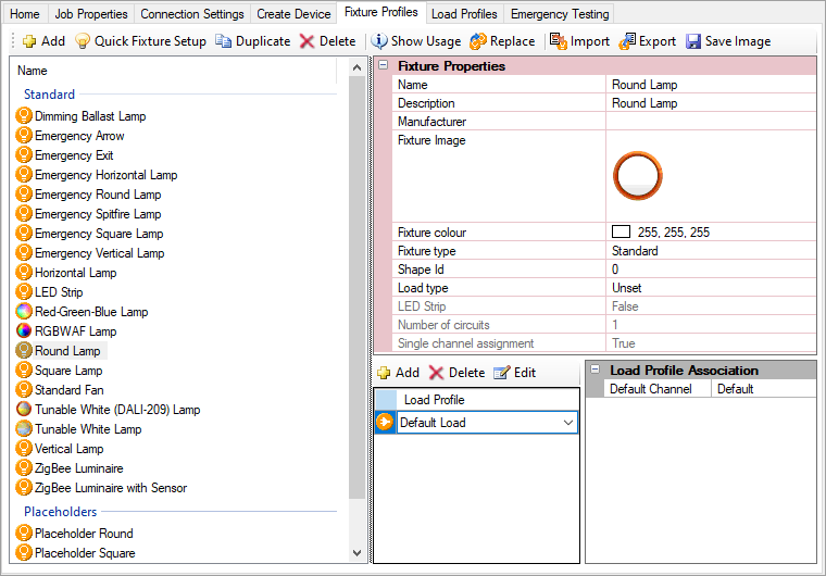
Fixture Profiles
There are two ways to open the Fixture Profiles editor:
-
On the floor plan window’s fixture palette toolstrip, click
 Add Fixture Profile to Palette.
 -
Select the job name at the top of the System View or Building View tree and click the Fixture Profiles tab in the Properties window.
The Fixture Profiles editor enables you to add fixture profiles (including the image), as well as duplicate, delete, show usage, replace, import, and export as needed. You can also add a Load Profile to each Fixture Profile.

Quick Fixture Setup
You can use the Quick Fixture Setup editor to add multiple custom fixture profiles in a single table:
-
Click
 Quick Fixture Setup
 -
Click in each in each cell or press F2 to enter the information into the table:
-
Code: Drawing ID
-
Description
-
Fixture Type:
-
Standard
-
WWCW
-
Dimming Driver
-
RGB
-
RGBWAF
-
WWCWOC
-
Custom
-
-
Load Type:
-
Unset
-
DALI
-
1-10V
-
DSI
-
DMX
-
Incandescent (no driver)
-
Non-Dimmable Lamp (electronic driver)
-
LED (LE compatible electronic driver)
-
LED (TE compatible electronic driver)
-
LED (LE/TE compatible electronic driver)
-
Halogen (LE compatible electronic driver)
-
Halogen (TE compatible electronic driver)
-
Halogen (LE/TE compatible electronic driver)
-
Switched Load
-
Ceiling Fan
-
Curtains
-
Motor
-
LED PWM
-
-
LED Strip: Tick the checkbox for LED strip fixtures.
-
Load: Channel load in Units
-
Unit: Select Watts or Watts/m (LED strips only)
-
Power Factor: The active power divided by the apparent power.
-
Lamp Life (hours)
-
Colour: Fixture colour on the floor plan.
-
Icon: Fixture icon on the floor plan.
-
-
You can click in the first column to select a row and
 Duplicate or
  Delete it.
 -
Click when complete.
Alternatively, you can add user-defined fixture profiles using the main Fixture Profiles editor by clicking the ![]() Add icon.
Add icon.
| After creating custom profiles, remember to save the changes to your job file. |
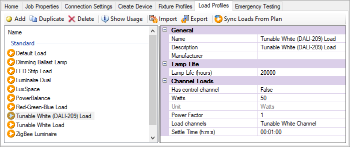
Load Profiles
To access the Load Profiles editor, select the job name at the top of the System View or Building View tree and click the Load Profiles tab in the Properties window.
The Load Profiles editor enables you to add load profiles, as well as duplicate, delete, show usage, import, and exported as needed. You can also describe the type of load, number of channels, lamp life, and wattage.


