Temperature Editor
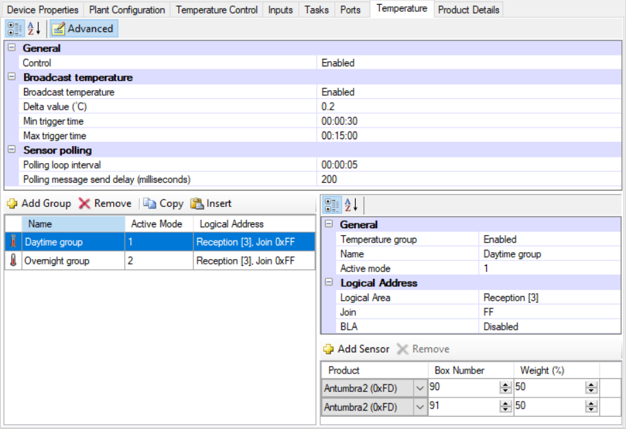
The Temperature editor contains the following settings to configure temperature aggregation and remote temperature broadcast:
-
General
-
Broadcast temperature
-
Sensor polling (Advanced)
|
Initially only the basic fields are shown. Most standard setups do not require advanced properties, but you can reveal all fields by clicking the button. Displayed fields can be sorted in one of two ways by clicking the following icons: Refer to the property description pane at the bottom of the editor for explanations of each property. |
The DDFCUC polls and aggregates the temperature measurements from user interfaces on the network and can then broadcast this calculated remote temperature.
External conditions can affect each space differently depending on its location in the building. Every Philips Dynalite user interface includes a temperature sensor, allowing you to choose the most representative location from which to measure the current temperature and trigger heating or cooling. This can be time-based - measuring from living areas in the daytime and the bedroom overnight to reflect occupant behaviors most accurately - or averaged readings from groups of sensors (multi-temperature aggregation) for an accurate overall representation of temperature in the relevant space(s).
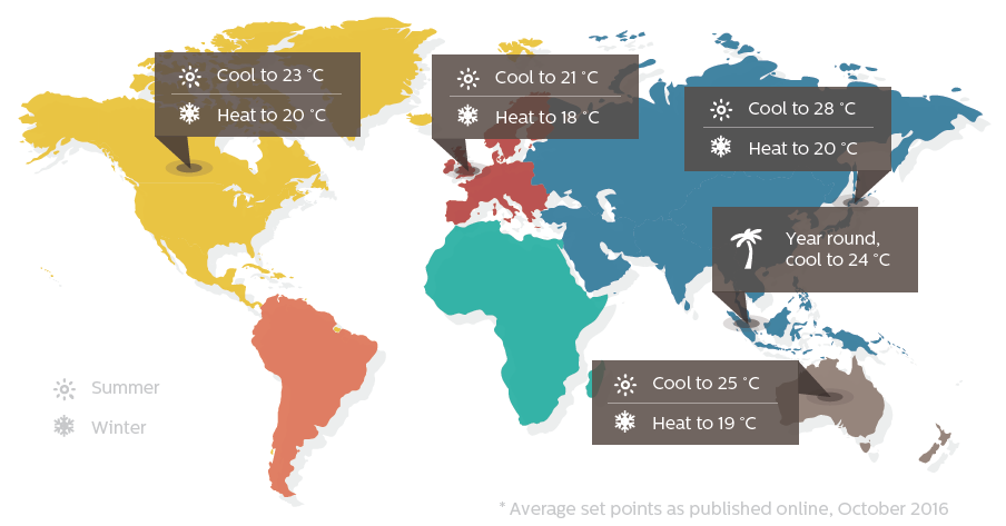
Regions across the world generally cool and heat their spaces to seasonal setpoints, nominally set as 'summer minimum' and 'winter maximum' levels.

Multi-Temperature Aggregation
Reading a combination of different temperature sensors (active modes) at different times of the day provides a more meaningful temperature for an area considering temperature gradients and intended usage. The DDFCUC polls individual sensors using DyNet2 physical messages for their actual temperature readings. These values are assigned a configurable percentage weight and averaged to create the aggregated temperature value.
A broadcast temperature message can then be sent from the HVAC area.
A logical message to change the active mode determines which group of sensors to read.
For example, there are typically two active modes:
-
Daytime:
1C,02,24,48,00,01,FF(Active mode 1) -
Overnight:
1C,02,24,48,00,02,FF(Active mode 2)
-
Set the applicable [_properties] (see below).
-
Click
 Add Group,
  Remove,
  Copy, or
  Insert to create the required sensor groups.
 -
Enter the temperature group’s Name.
-
Enter the group’s Active Mode number.
-
Select a Logical area, Join and BLA, if applicable. This is the area that sends the aggregated temperature message to the trunk network.

-
Click
 Add Sensor for each user interface to include in the temperature group (up to eight).
You can select Antumbra2 (0xFD) for Antumbra and Revolution panels as they use the same communication module (DACM). -
Enter each device’s Box number.
-
Enter each device’s temperature reading Weight (%). The total of all selected interfaces must add up to 100%.
-
Press F12 or click
 Save to Device.
Editor Properties
| Property | Description |
|---|---|
General |
|
Control |
Enabled/Disabled. Used to enable/disable the multi-temperature aggregation feature. |
Broadcast temperature |
|
Broadcast temperature |
If Enabled, the device broadcasts aggregated temperature messages. |
Delta value (°C) |
The minimum temperature change required to trigger an aggregated temperature message. |
Min trigger time |
The minimum time that must elapse to trigger an aggregated temperature message. |
Max trigger time |
The maximum time before triggering an aggregated temperature message regardless of Delta value (°C). |
Sensor polling |
|
Polling loop interval |
The time between requests to read all temperature sensors. |
Polling message send delay (milliseconds) |
Delay between sending requests to each temperature sensor. |
Sensor Group Properties
| Property | Description |
|---|---|
General |
|
Temperature group |
Enabled/Disabled. Used to enable/disable the temperature group. |
Name |
Temperature group identifier |
Active mode |
Index number for setting the active temperature group. This is sent via a DyNet1 User Preference message. Up to 16 temperature groups are supported. |
Logical Address (Sensor group) |
|
Logical Area |
Area where the temperature sensors are located. |
Join |
_The static join of the device. |
BLA |
Enabled/Disabled (Base Link Area) |