Properties Window
This window displays configuration settings under each property editor tab. These editors vary depending on the item(s) selected in the View Window, and contain many configurable settings.
| Refer to the Property Editors tables for a complete list of editors specific to each view. |
Example Property Editors
Below are examples of item-specific property editors:
-
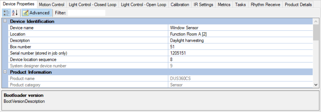
Device Properties for a device selected (System View)
-
Presets for an area (Areas View)
-
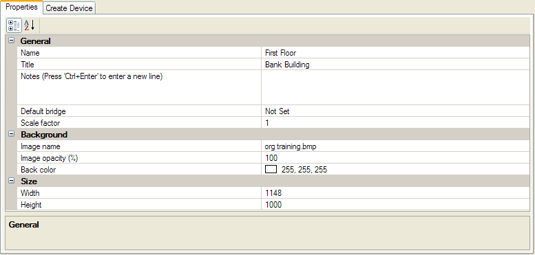
Properties for a floor plan (Building View)
-
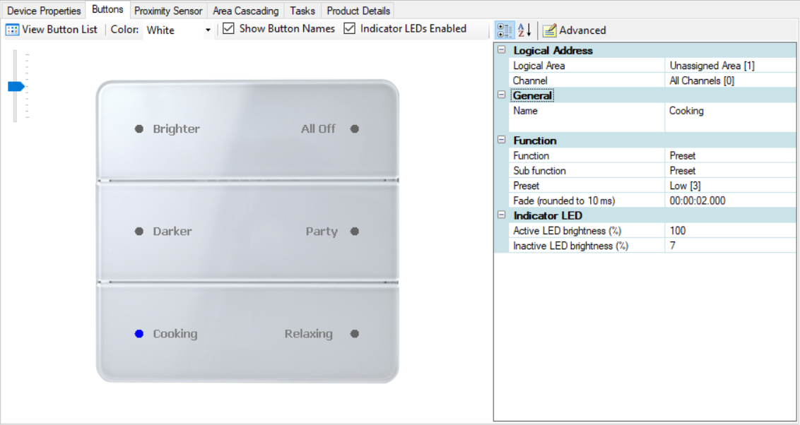
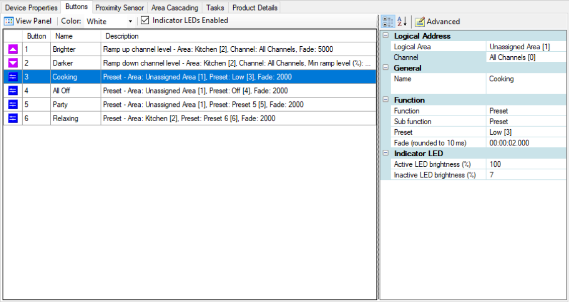
Buttons for a user interface (System View)
-
Outputs (circuit/lamp driver) for a load controller (System View) or area (Areas View)
Device Properties (System View)
Each editor has a unique list of properties and tools to help you easily configure each item. The Device Properties editor is available for all devices.
The Device Properties toolstrip has the following buttons and fields:
-
 Categorized - Sorts properties into related categories
 -
 Alphabetical - Sorts properties in ascending/descending alphabetical order
 -
 Advanced - Displays advanced properties in addition to the basic properties
 -
 Filter - Displays only properties that match the entered text

Preset Editor (Areas View)
The Preset editor includes Level Adjust sliders for each channel to set up different scenes and assign them to a preset Number. You can select the ![]() Flash checkbox to flash a channel on/off, or the
Flash checkbox to flash a channel on/off, or the ![]() Level Exclude checkbox to exclude a channel from the preset.
Level Exclude checkbox to exclude a channel from the preset.
To exclude a preset from user interface apps that read the project.xml file in the Ethernet Gateway, set the Preset Type to Hidden.
We recommend modifying preset levels in Areas view. If modified in a device, they will need to be synchronized.
Preset |
P1 |
P2 |
P3 |
P4 |
P5 |
P6 |
P7 |
P8 |
|---|---|---|---|---|---|---|---|---|
Default Light Level |
100% |
70% |
40% |
0% |
80% |
60% |
50% |
20% |
The following buttons and fields are available in the toolstrip:
-
 New ⏷ - Adds new presets either singularly or in a range. Also Toggle and Panic presets can be modified.
 -
 Duplicate - Creates a new preset that is the duplicate of the selected preset.
 -
 Delete Preset - Deletes the selected preset. Presets can only be deleted from the end of the list of presets.
 -
 Copy - Copies the selected preset.
 -
 Paste - Pastes the copied preset to; replace selected preset levels or create new presets.
 -
 Synchronize - Synchronizes the device preset tables with the area preset table for circuits currently assigned to channels in the selected area.
 -
 Request Levels - Requests the currently active levels.
 -
 Save to Device(s) - Saves modifications to the device.
 -
Action:

-
Mute - Preset does not send a message onto the network
-
Send Levels - sends Channel Level messages
-
Send Presets - sends Preset messages
-
-
Levels:

-
Independent - channel levels are modified independently
-
Relative - channel levels are modified together relative to current positions
-
Tied - channel levels are modified together at the same value
 *Percent - If ticked, channel levels display as a percentage. Otherwise they are shown as a value (0-254).
-
-
 View Table/List
-
View Table displays channel levels in table format, and enables you to flash channels, exclude channels, or enter and adjust channel levels.
-
View List displays channel levels as a list, and enables you to copy multiple channel level values and paste as text.
-

Floor Plan Properties (Building View)
Plan properties are displayed in the Properties window when a plan is selected in Building View. The Plan Properties Editor contains the details for each plan in your project and how each plan image is to be displayed in the Floor Plan Window. A Plan has the following properties:
-
Name – Name given to the floor plan.
-
Title – Title shown on the Floor Plan window for the selected plan.
-
Notes – Section for notes that can be used to write about the selected plan.
-
Default bridge – Each plan can have a default bridge. The
 default bridge is indicated in the Building View with a small tick on the top left of the icon. The first bridge added to the plan is automatically set as the default bridge. To change the default bridge right-click on the new bridge or select it on the Plan Properties Editor.
When devices are added to the plan they will appear under the default bridge in System View. -
Scale Factor – This factor is used to scale new icons when adding them to the plan. The scaling factor is automatically set when an icon is proportionally scaled in the plan.
-
Image name – File name of the background image uploaded as floor plan.
-
Image Opacity – Sets the opacity (transparency) of the background image
-
Background Color – Sets the background color for the image. Select the background color by clicking on the drop-down list.
-
Width and Height – The plan size is automatically adjusted to the size of the background image when the background is set. There is a minimum value that can be entered for the plan width and height to ensure that icons and regions still fit on the plan. CAD drawings should be stripped of unnecessary components and layers and saved as WMF.
Max raster image resolution: 2400 x 2400 pixels.
Recommended file size: <5 MB.You can modify the size and position of the background images with the
 >
>  Edit Background Image option on the Floor Plan window toolstrip. Right-click the background image to exit edit mode.

Input Device Editor - Buttons
Button panels are the most common type of user interface in a Dynalite system. The Buttons editor can display an image of the user interface or a list of buttons and assigned functions.
Select a button to configure its function(s) and the type of press/release action to triggers each function.
Refer to Functions for a complete list of available functions.


Outputs Editor
The Outputs editor is available both for applicable devices and for areas.
Device Outputs Editor
You can access the device Outputs editor is accessed by selecting a load controller in System/Building View and clicking the Outputs tab. This editor displays each of the controller’s connected circuits and/or lamp drivers, along with their associated settings and properties.
You can enter a name, area, and channel assignment for each output. Circuits/lamp drivers can be flashed from the editor to confirm their location.
Selecting the ![]() checkbox in the Switching column enables you to restrict the output to switching only, so any level sent above zero will set the channel to 100%.
checkbox in the Switching column enables you to restrict the output to switching only, so any level sent above zero will set the channel to 100%.
If two circuits/lamp drivers are assigned to a single channel, they will act in unison and one will be marked as a duplicate.

Area Outputs Editor
To access the area Outputs editor, select one or more areas in Areas View and click on the Outputs tab in the Properties window.
This editor displays the channel information from an area perspective, providing similar columns to the device Outputs editor, and can also flash channels and configure some channel-specific properties. However, area and channel numbers are not editable in this view.
