Replacing a Legacy 100BT
Where existing installations have a legacy DDNG100BT or DMNG100BT (100BT) gateway, you can replace these devices with EGs. However, because the devices have different properties, you must copy the individual property values between the devices.
The 100BT communicates over Ethernet using one of the following five modes:
-
Passive TCP - The local 100BT awaits a TCP connection made by a remote 100BT or PC application. DyNet packets are transported using TCP packets. This option is good for point-to-point networks over the internet.
-
Active TCP - The local 100BT initiates and maintains a TCP connection to a remote 100BT. DyNet packets are transported using TCP packets.
-
UDP - The local 100BT relays DyNet messages to multiple other 100BTs. DyNet packets are transported using broadcast UDP packets. This option is good for multi-device networks within an intranet.
-
HTML - The 100BT hosts basic web pages that can be used to send commands to, and show status of, the Dynalite network. A Common Gateway Interface (CGI) interface provides dynamic content for these pages. This option provides a customized user interface to the Dynalite network.
-
Telnet - The local 100BT awaits a TCP connection made by a remote Ethernet-enabled device or PC application. The DyNet Text protocol can be used to send commands to, and retrieve status from, the Dynalite network. This option is good for integration to Ethernet-enabled third-party devices.
The table below details functionality on each of the IP transport layers:
| Mode | TCP | UDP | HTML | Telnet |
|---|---|---|---|---|
Application |
HTML, JavaScript, Flash |
Telnet |
||
Presentation |
CGI |
DyNet Text Protocol |
||
Session |
DyNet |
DyNet |
HTTP |
TCP |
Transport |
TCP |
UDP |
TCP |
TCP |
Network |
TCP |
UDP |
TCP |
TCP |
Data Link |
IP, ARP, DHCP, AutoIP |
|||
Physical |
Ethernet |
In operational systems, the 100BT was used primarily for the following applications:
-
Ethernet access point - the 100BT provides an intranet web interface to DyNet using CGI commands. With a port exposed to the internet, it can be used for remote monitoring of sites.
-
Ethernet bridge - the 100BT provides an Ethernet connection between DyNet RS-485 spurs to establish a trunk connection or bridge gaps where it is not practical to run DyNet cabling.
| The EG provides the option to connect either over Ethernet using the IPv6 default service address, or over DyNet. The initial connection to the 100BT must be over DyNet until TCP properties are entered and saved to the device. |
-
Plug the EG into a DyNet port on a spur to provide power and communications via the RS-485 network.
-
Plug the commissioning PC into a USB PC node, then plug the USB PC node into a DyNet port on the same spur.
-
Open the job file in SB and select the job name.
-
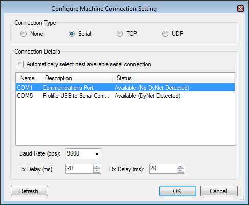
Open the Connections Settings editor, click the button, and connect using a serial connection.
-
Click
 Insert Devices from Network.
 -
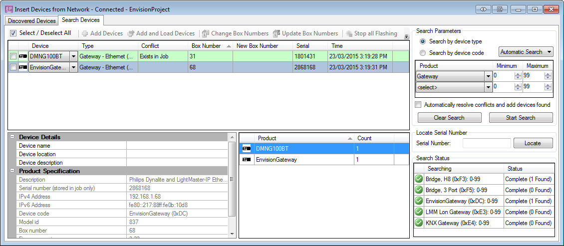
Press the service switch on the EG to sign the device on to the network, or Search by device type for Product > Gateway. The EG now appears in the Discovered Devices list.
-
Click
 Add and Load Devices and close the dialog box. The EG appears in the job.
 -
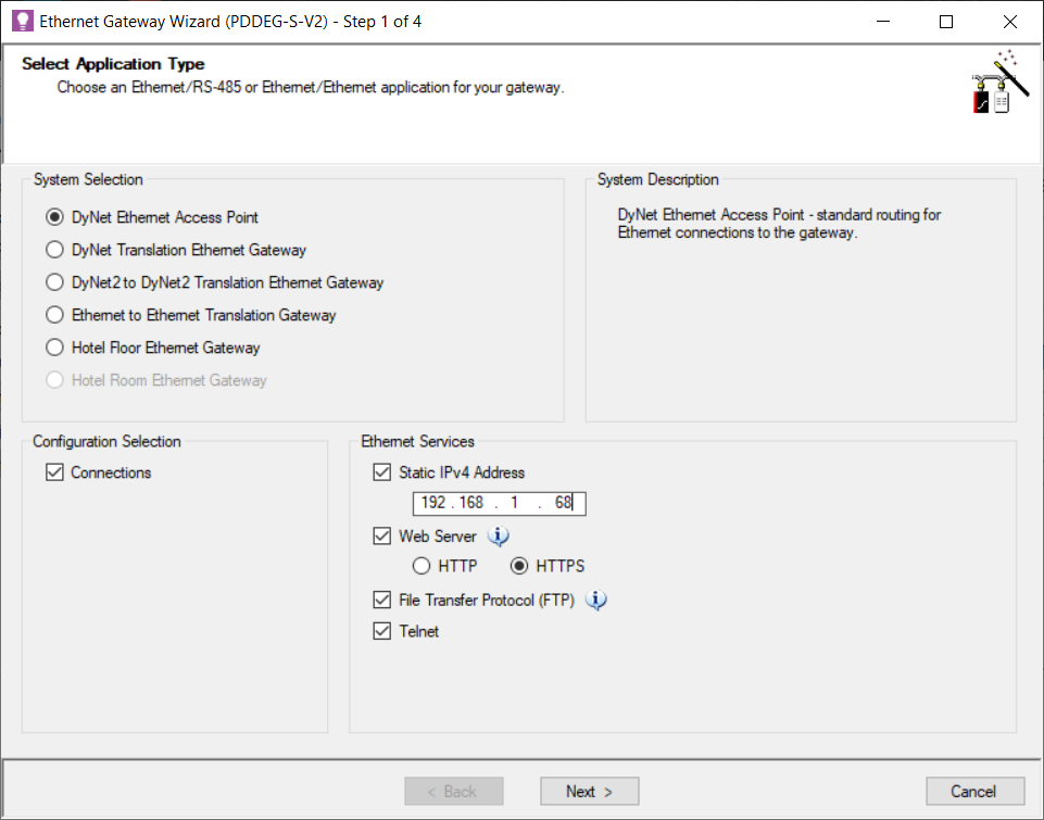
Select the 100BT and copy the relevant properties to the EG (in Device Properties, ensure that you copy the 100BT’s Local IP Address to the EG’s IPv4 Address).
-
Select the EG and press F12 or click
 Save to Device.
 -
Right-click the EG in the device tree and select
 Bridge Configuration Wizard or press Alt+W.
 -
Select DyNet Ethernet Access Point and click the button.
-
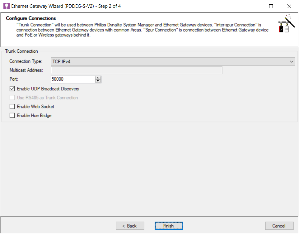
In Connection Type, select TCPv4 and set the Port to 50000. Click the button.
-
Select the EG and press F12 or click
 Save to Device.
 -
Right-click the EG and select
 Upload Configuration > Upload Logical Configuration (
project.xml). Refer to Commissioning > Ethernet Access Point > Wi-Fi access. -
Delete the 100BT from the job.
-
Click File >
 Save to save the job to your PC.
-
Open the job file in SB and select the job name.
-
Open the Connections Settings editor, click the button, and connect using a serial connection.

-
Click
 Insert Devices from Network.
 -
Press the service switch on the EG to sign the device on to the network, or Search by device type for Product > Gateway. The EG now appears in the Discovered Devices list.

-
Click
 Add and Load Devices and close the dialog box. The EG appears in the job.
 -
Select the 100BT and copy the relevant properties to the EG (in Device Properties, ensure that you copy the 100BT’s Local IP Address to the EG’s IPv4 Address).
-
Select the EG and press F12 or click
 Save to Device.
 -
Right-click the EG in the device tree and select
 Bridge Configuration Wizard or press Alt+W.
 -
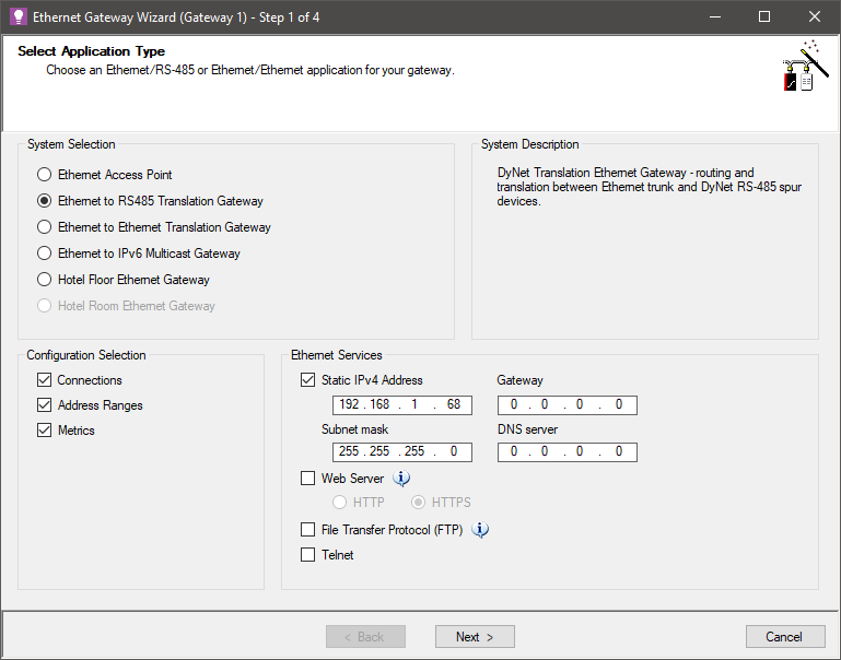
Select Ethernet to RS-485 Translation Gateway and click the button.
-
Under Trunk Connection, set the Connection Type to TCPv4 and the Port to 50000.
-
Under Inter-spur Connection, set the Connection Type to TCPv4 and the Port to 50001, and ensure that Enable UDP Broadcast Discovery is ticked. Click the button.
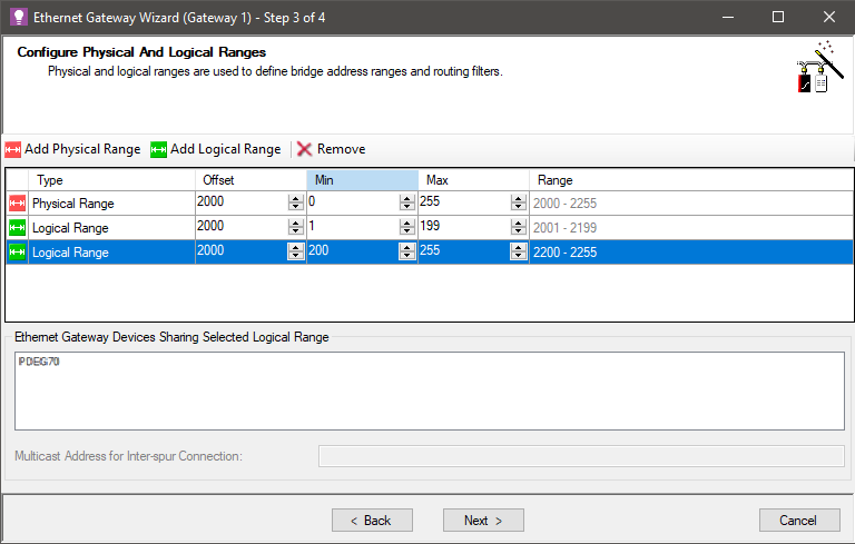
The Enable UDP Broadcast Discovery checkbox enables the UDP discovery port (9998) used by SB to find the bridges in the system (listed in the Connection Settings editor under Ethernet Trunk Connection Settings). It also enables DynamicTouch access. -
Click and enter Offset, Min and Max values.
-
Click and enter Offset, Min and Max values. Primary address Min value must be 1 or 0 (see note below).
-
OPTIONAL: Click again to enter address ranges that are common to multiple EGs. The range defined by the Min and Max values must not overlap with the other logical ranges.
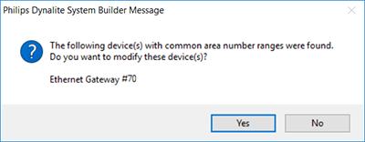
SB lists the EG devices that it finds in the job that share common address ranges. The address ranges must match exactly.
-
Click the button.
The primary logical range for the spur can also be changed to start from 0 if you want to allow for Area 0 (All Areas) messages to be sent from the trunk. You must enable the Area Zero Transmit property on the port record for the EG. Spur devices may require further configuration to support this.
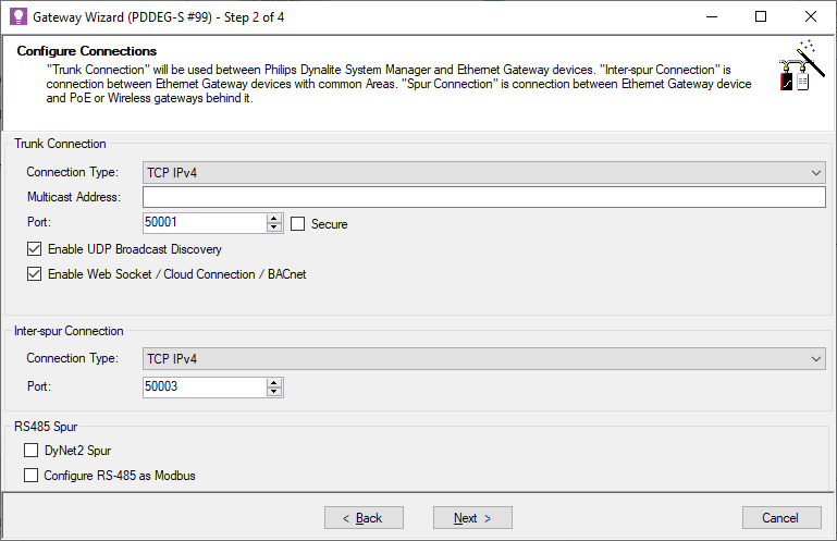
A common logical range enables the system to address areas that span multiple spurs. A common physical range enables devices to appear on a single spur when attached to different EGs. -
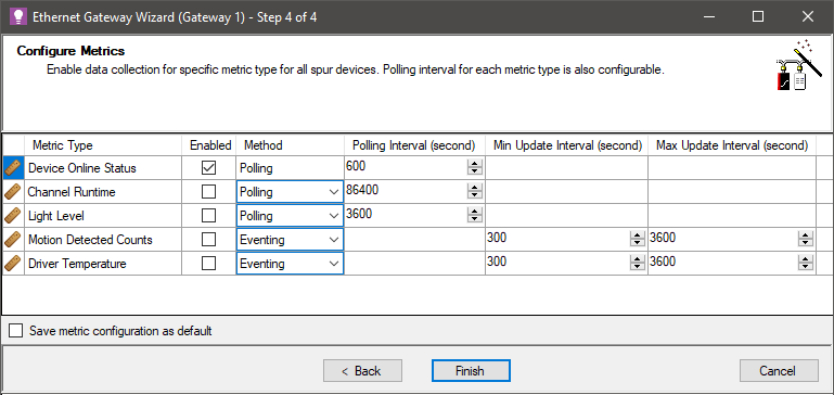
Click the button to accept the default metrics for devices and channels on the spur. You can tick/untick the Enabled checkbox or adjust the Polling Interval for each metric, if applicable.
-
Click the button.
-
A popup message indicates the other EGs that must have their settings saved. Click .
-
Select the EG and press F12 or click
 Save to Device.
 -
Click and drag all devices from under the 100BT to under the EG.
-
Delete the 100BT from the job.
-
Click File >
 Save to save the job to your PC.