DALI addressable controllers
Overview
DALI addressable controllers have multiple loads (drivers) that can be controlled independently on each circuit (DALI line). The procedure for commissioning DALI controllers is the same as for non-DALI controllers with an additional enumeration step.
The standard procedure involves enumerating the DALI network, entering the circuit/driver properties, locating drivers, grouping related circuits into areas, and then recalling channel levels and preset scenes for those areas.
The load controller takes care of message translation between the DyNet and DALI networks. Once load controllers are commissioned the project has a solid foundation on which any number of operational features can be applied.
DALI addressable controllers act as gateways that link multiple DALI networks together via DyNet. They can operate in three modes:
-
Short address mode
-
Group and scene mapping mode
-
Broadcast mode
After adding a DALI addressable controller to the project, the controller appears on the Dynalite network as a 64 to 192 channel load controller. Some DALI addressable controllers have selectable outputs that can be configured as 1-10V Analogue, DSI, DALI Broadcast or DALI Enumerated.
DALI-2 driver controllers (DDBC120-DALI and DDBC320-DALI) have advanced functionality and are designed for DALI enumerated circuits. Additional metrics are available when paired with DALI-2 certified drivers, such as Driver Temperature, Total Energy Consumption (DALI), and Power (DALI).
| DALI addressable controllers have a built-in power-saving relay associated with each DALI output. When all lamps on a DALI line are at 0%, the relay automatically cuts power to the line, eliminating unnecessary standby power consumption from the lamp drivers. |
Initial controller checks
Prior to configuring the controller, the installer can check the wiring by pressing the service switch three times within four seconds. This causes all drivers that are operational and correctly wired to the controller to drive their lamps to 100% brightness, providing immediate visual confirmation.
You can perform a DALI network check at any time by pressing the controller service switch four times within four seconds. The controller will run a sequence that dims all the drivers on the network to 0%, then 50%, then 100%, cycling every 5 seconds for a total of 5 minutes. This enables the user to visually check that all drivers connected to the DALI network are functioning correctly. Resetting the controller stops the sequence.
The relevant service switch functions are:
-
1 push = Network sign-on
-
3 pushes = All channels 100%
-
4 pushes = All channels run test mode flash sequence for 5 minutes
-
Push and hold for 4 seconds and release = Device reset
-
1 push = Network sign-on
-
Push and hold for 4 seconds and release = Device reset
-
1 push on a DALI line switch = Toggle all channels between 100% and 0%
-
Push and hold a DALI line switch for 4 seconds = Line channels run test mode flash sequence for 5 minutes
DALI addressable configuration
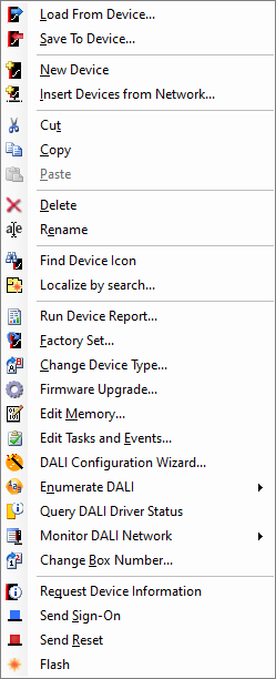
Controller functions are accessible from the System view toolbar when the controller is selected, or by right-clicking the DALI load controller to access the context menu.
You can hover the mouse cursor over each toolbar button in System Builder to reveal a tooltip describing its function.


Complete the following configuration tasks:
-
Add a controller to the job
-
Enter device properties
-
Enumerate drivers
-
Configure driver properties
-
Locate drivers
-
Assign drivers to areas and channels
-
Configure lighting scenes
-
Maintain DALI drivers
| These tasks can be performed using the System Builder editors or the DALI Configuration Wizard. Less experienced users may prefer to use the wizard for initial configuration and maintenance tasks. |
Adding a controller to the job
-
Open a new job in SB and connect to the network.
-
Add the device to your project using one of the following two methods:
-
 Insert Device from List (Ctrl+D) - to precommission the device.
 -
 Insert Device from Network (Ctrl+L) - to search for an online device or sign-on the device.
-
After searching the network for the controller, you can add it to the job by clicking ![]() Add Devices (add with default data) or
Add Devices (add with default data) or ![]() Add and Load Devices (load data from device). For previously enumerated DALI networks, if SB asks: "Do you want to load device data?", click the button.
Add and Load Devices (load data from device). For previously enumerated DALI networks, if SB asks: "Do you want to load device data?", click the button.
| You can always connect System Builder using a serial connection to the RS-485 port on a device. However, with an Ethernet gateway or Ethernet-enabled load controller, you can also connect using IPv6 or IPv4. You have the option to use the UDP multicast default service address or alternatively, refer to the steps for setting up a TCP/IPv4 port and adding a user in the Ethernet Gateways Commissioning Guide. |