Controls
The Control frame contains several groups of controls for both the Floor Plan and the selected area, fixture, or device.
Area Name
| This feature requires the Modify Area permission. |
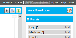
To rename the selected area, click the ![]() Rename button.
Rename button.
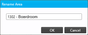
In the Rename Area dialog, enter a new name for the area and click .
Presets
By default, this group contains 8 predefined preset scenes. Click a preset to apply it to the selected area.
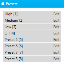
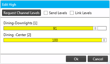
You can modify a preset for the selected area by clicking Edit next to the preset name to load the Edit Preset dialog.
-
Click to copy the current channel levels to the preset.
-
Select Send Levels to immediately apply channel level adjustments to the area in real time.
-
Select Link Channels to apply a single channel level to all channels in the area.
-
Drag each channel’s slider to the desired level.
-
To save your changes, click .
Channels
Change individual channel levels for the selected area by dragging the sliders, or click Link to control all channels in the area with a single slider.

Current light levels are indicated by the color of each lamp on the Fixtures layer and each area on the Light Map layer.
Sensor Timeout
-
Select a timeout from the dropdown list (10 seconds to 60 minutes, or Manual to set a custom duration)
-
Click to apply your changes.
-
Click to set the timeout to the default duration.

Auto Sensor Calibration
This group is only visible for areas containing sensors with light level detection, and provides a simple calibration method for all applicable sensors within the selected area.
-
Obtain an accurate reading of the current light level in the area.
-
enter this value in the Lux field and click .
All sensors in the area will adjust their light level detection accordingly.

Sensor Lux Levels
This group is only visible for areas containing sensors with light level detection.
Each sensor in the area is displayed with its most recent lux level reading.

Sensor Temperatures
This group is only visible for areas containing Antumbra UIs with temperature broadcast enabled, and shows the most recent temperature reading from each UI.

| PDTS and Revolution temperature readings will be added to this group in a future update. |
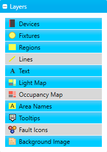
Layers
This group controls which layers of content are visible in the Floor Plan. Click on any layer to toggle it:
-
Devices - Controllers, UIs, sensors, gateways, distribution boards, etc.
-
Fixtures - Lamps and drivers
-
Regions - Areas
-
Lines - Visual links between fixtures and/or devices, usually to indicate wiring or shared control channels
-
Text - Additional text labels added to the floor plan
-
Light Map - Indicates the current average channel levels for each area
-
Occupancy Map - Indicates the current occupancy levels for each area
-
Area Names - Adds a name label to each area
-
Tooltips - Controls whether tooltip popups appear when the cursor hovers on an area, fixture, or device.
-
Fault Icons - Displays a red exclamation symbol over any fixtures or devices with current faults.
-
Background Image - Displays the floor plan map image
|