Text Over IP
The EG can integrate with third-party devices by sending and receiving user defined text messages in ASCII or binary protocols. Text messages can be communicated over a TCP or UDP connection. For example, sending text to an IP address to control AV equipment.
There are two types of instructions:
-
A SendPF instruction is written in a task to send numbers to text ports from tilde locations.
-
A SendP instruction is written in a task to define the string of ASCII or hexadecimal packets.
-
Add an EG to the System Builder job.
-
If connecting to a third-party device using IPv4, ensure the EG is configured in the Port Editor:
-
Enter a static IPv4 address,
Or: -
Acquire a dynamic IP address by setting the Use static IP address property to False.
-
-
In the Ports editor, add a new port and set the Port type to Text and Binary Integration. Make sure the Mode, Port Number, and Protocol properties are correct for connecting to the third-party device (Refer to Ports editor port properties).
-
Open the Tasks editor and enter the SendPF or SendP task instruction. The instruction has the following format:
-
SendP (Port Type, Port Index, Data, …)
-
Port Type: 1=Comm port (supported but cannot add), 2= IPv4 Port, 3= IPv6 Port.
-
Port Index is a sequence number starting from 1 for each port type.
(The Port Type and Port Index can be found in the port list) -
Data supports up to 126 characters in ASCII or Hex.
-
-
SendPF (Port Type, Port Index, "%c %d %u %s %x", ~1,~2,~3…)
Where %c, %d, %u, %s, %x are format specifiers.
-
-
Test compile the task and write to device.
For sending text using the printf format, SendPF supports the same instructions as SendP and more. This allows values to be easily sent from tilde locations.
The SendPF command will allow for up to 8 tilde memory locations to be specified where the value of the parameters (by using the % symbol) will be output.
-
%d: Output an integer as a signed decimal number.
-
%u: Output for decimal unsigned integer (int).
-
%x: Output an integer as an unsigned hexadecimal number.
-
%c: Output a character (char). No null character is added.
-
%s: Outputs a string. No null character is added.
To send a 2-byte number, append length 'l' (i.e. %ld). This allows signed numbers greater than +/-127 and unsigned numbers greater than 255
To send a 4-byte number, append length 'll' (i.e. %lld).
SendPF text commands
| Instruction examples | |
|---|---|
Direct Text |
IPv4 port, Port Index = 1, Data ="sendthistext" If the text requires being null terminated then add '%c' after the string and use '0' as parameter If the text requires a carriage return then add '\r' after the string |
From a declaration at a label |
|
From Tilde Memory |
Task5() Output will be Area is <Area Number in the DyNet message> |
SendP Commands
| Instruction examples | |
|---|---|
Direct Text |
IPv4 port, Port Index = 1, Data ="sendthistext" If the text requires being null terminated then add an additional 0 parameter If the text requires a carriage return then add an additional 0x0D parameter |
Hex Packets |
SendP(2, 1, 0x68, 0x65, 0x6c, 0x6c, 0x6f, 0x77, 0x6f, 0x72, 0x6c, 0x64) |
From Tilde Memory |
Task2() LDA #0x41 //'A' Load 6 Bytes Into Tilde String in memory must be null terminated. The output will be ABCDE. With an offset in the index register. The output will be BCDE. With a specified length. If L=0x03 then output will be ABC With an offset in the X register and a specified length. If L=0x03 then output will be BCD. |
From a declaration at a label |
TestLabel: SendP(2, 1, "VWXYZ", 0) Send from label. String must be null terminated. The output will be VWXYZ. With an offset in the index register. If X=1 then output will be WXYZ. With a specified length. If L=0x03 then output will be VWX. With an offset in the X register and a specified length. The output will be WXY. |
Receive text commands
Incoming text over IP messages trigger a Start task instruction. The scanf format (in the table below) is used to define the received text. The instruction allows you to specify up to 8 tilde memory locations to store the value of the parameters (by using the % symbol).
| Instruction example | |
|---|---|
Format |
|
Specifiers |
|
Examples |
Start("Hello") Start("Temp A%d %d.%d",~7,~6,~5) for example: Temp A5 24.5 Start("B. %*4s F%d %d.%d",~4,~5,~6) for example: Temp F6 23.7 Start("Volume%d %ld",~20,~21) for example: Volume5 337 |
Receive binary commands
The EG now supports receiving third party binary/hex messages over IP. System Builder 3.11.7 or later is required to take advantage of this feature.
The Startx command can be used in a task to listen to third-party binary/hex messages.
For example: StartX(0x01,x,0x03,x,x,x,0x07)
The command features:
-
Decimal or hex (using 0x) byte values.
-
Character "x" for non-matching bytes.
A dedicated TCP/IPv4 port configured as Text and Binary Integration is required in the EG.
CoolAutomation integration
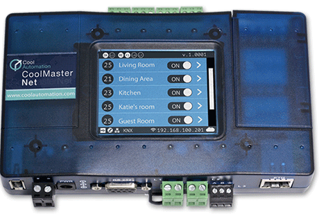
Integration with the CoolAutomation central HVAC control system enables centralized and in-room HVAC control and monitoring. Integration is performed with a CoolMasterNet bridge, dedicated HVAC Ethernet Gateways and AntumbraDisplays in each room.
-
Request HVAC Status
(Channel 100: replies with all current settings in the HVAC unit). -
On/Off Specific/All HVAC units
(Channel 101: 0% = OFF, 1 - 100%= ON). -
Change the HVAC mode for specific/All units
(Channel 102: 0% = Cool, 1% = Heat, 2% = Fan, 3% = Dry, 4% = Auto, 5% = Aux Heat). -
Change the Fan Speed for specific/All units
(Channel 103: 0% = Low, 1% = Medium, 2% = High, 3% = Top, 4% = Auto). These channel levels are absolute, e.g. “Auto" is always 4% even if “High" or “Top" is disabled. -
Change the Louver Position (Swing) for Specific/All units
(not all indoor units support louver position)
(Channel 104: 0% = Horizontal, 1% = Vertical, 2% = Auto, 3% = 30°, 4% = 45°, 5% = 60°). -
Report error in the HVAC unit
(Channel 105: 0% = OK, 1-100% = Error) -
Display the Filter status (- or #) reported by the HVAC unit
(Channel 106: 0% = OK, 1% = Filter to be cleaned). -
Display and Change Set point temperature for specific/All units
(DyNet message sent from Antumbra). -
Display the Room temperature reported by the HVAC unit
(DyNet message sent from Antumbra).
-
Temperature is represented in degrees Celsius. Fahrenheit is not supported.
-
Only absolute integer values are supported at this stage.
CoolMasterNet Configuration
Firstly, the CoolMasterNet Bridge must have Line and Units configured by the HVAC installer.

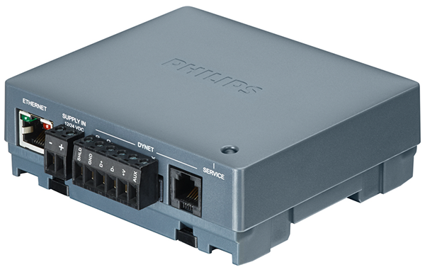
Ethernet Gateway Configuration
You need to add one or more EGs to the job in System Builder, then run the bridge configuration wizard to setup the Ethernet gateway(s) as an Access Point. One Ethernet Gateway can control up to 40 HVAC units.

To pass messages between the room controller and the CoolMaster system, each EG in the system must have an IPv4 port preconfigured as follows:
-
Port Type: Text and Binary Integration
-
Mode: Client
-
IP Address: IP address of the CoolMasterNet bridge
-
Port number: TCP Port of the CoolMasterNet bridge (Default: 10102)
-
Protocol: TCP
In the EG Tasks editor, select the CoolMaster Integration – EG.evt task template. Edit the task template settings to match the CoolMaster configuration. Some of the settings need to come from the HVAC installer.
Simulation mode
It is recommended to first test the CoolMaster integration by placing the CoolMaster gateway into simulation mode. In the EG task template, you can configure several simulated HVAC units. To enable them to start the Set simulation task in the EG. As a result, the CoolMaster gateway should be populated with the configured number of simulation units.
| The Swing and Fan Speed = Top functions are not supported in simulation mode. |
Logical Configuration
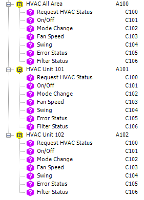
Each HVAC unit is controlled by a dummy area and corresponding channels for each action. The total number of areas should match the HVAC zones to be supported.
For example, Area 100 is for all HVAC units, Area 101 is for Room 1, Area 102 is for Room 2, etc. Each area must have seven channels numbered 100-106.
For more information refer to Dynalite FAQ #494: Coolmaster integration using PDEG as TXT gateway.
| You must use these specified channel numbers above. These are hard-coded in the task template and cannot be changed. |

AntumbraDisplay Configuration
CoolMaster integration requires one AntumbraDisplay per HVAC unit in the room or used by the facility manager for all HVAC units. The AntumbraDisplay polls the CoolMaster system every time the proximity sensor is triggered. This synchronizes the AntumbraDisplay with CoolMaster.
-
With the AntumbraDisplay selected, open the Tasks tab.
-
Click , then
 Coolmaster Integration - Antumbra.evt, and click .
 -
In the task template, set Parameters > Dynet HVAC Area to the correct logical area for the HVAC.
-
Enter 0 for any modes and fanspeeds not supported by your HVAC unit.
-
Open the Device Properties tab and make the following changes:
-
Default Parameters > Temperature unit: Celsius(C°)
-
Default Parameters > Minimum/Maximum temperature setpoint: as specified by your HVAC system.
-
Temperature Sensor > Broadcast Temperature: Disabled
-
-
Open the Display and Buttons tab and ensure that properties are enabled, then configure the display settings:
-
Configure Top > Display type to Current Area Temperature and select the correct Logical Area for the HVAC.
-
(Optional) Configure the middle display to show the HVAC error status:
-
Set Middle > Display Type to Multi-channel level icon.
-
Set Minimum channel level to 0% and Maximum channel level to 1%.
-
Click Icons, then click the button to open the Antumbra Icon Library.
-
Select
 Current Configuration and set General > Count to 2.
 -
Change each icon to an appropriate indicator (you can use custom icons if desired):
-
Item 1 - Icon: No Error
-
Item 2 - Icon: Error
-
-
Click to continue.
-
Set Middle > Logical Area to the correct area for the HVAC.
-
Set Middle > Channel to the HVAC error status channel (channel 105).
-
Set Bottom > Display type to Temperature setpoint. Select the correct Logical Area for the HVAC.
-
-
-
Configure buttons with the desired/available functions for your HVAC system:
-
This example shows the steps to configure a fan speed control button:
-
Select Function: Task and Sub function: Task local.
-
Select Control type: Start task.
-
Select Task: Fan [3].
-
Select Display type: Multi-channel level icon.
-
Set Minimum channel level and Maximum channel level to the lowest and highest available fan settings (See Supported CoolMaster actions).
-
Click Icons, then click the button to open the Antumbra Icon Library.
-
Select
 Current Configuration and set General > Count to the number of fan speed options.
 -
Change each icon to an appropriate indicator (you can use custom icons if desired). Ensure that the icons match each fan setting.
-
After choosing the icons, click to close the window.
-
Set Logical Address > Logical Area AND Display > Logical Area to the correct area for the HVAC.
-
Set the Logical Address > Channel AND Display > Channel to the fan speed channel. (See Supported CoolMaster Actions at the start of this topic.)
-
Set Display > Join to FE (this is the join value for all CoolMaster task messages).
-
-
Repeat the previous step for the Indoor Unit On/Off and Change Mode tasks if required (See Supported CoolMaster actions for channel numbers and level settings).
-
For a filter status button/indicator:
-
Set the Function and Sub function to Channel level.
-
Set Channel Level (%) to 0%. This allows the button to reset the "Filter requires replacement" status.
-
Set Display Type to Multi-channel level icon.
-
Set Minimum channel level to 0% and Maximum channel level to 1%.
-
Click Icons, then click the button to open the Antumbra Icon Library.
-
Select
 Current Configuration and set General > Count to 2.
 -
Change each icon to an appropriate indicator (you can use custom icons if desired):
-
Item 1 - Icon: Filter OK
-
Item 2 - Icon: Filter requires replacement
-
-
Click to continue.
-
Set Logical Address > Logical Area AND Display > Logical Area to the correct area for the HVAC.
-
Set the Logical Address > Channel AND Display > Channel to the fan speed channel (See Supported CoolMaster actions).
-
-
For temperature setpoint control:
-
Configure two buttons with:
-
Function: Temperature setpoint
-
Sub function: Increment temperature setpoint / Decrement temperature setpoint
-
Step: 1.0°C
-
Appropriate temperature up/down icons from the Antumbra Icon Library.
-
Logical Address > Logical Area set to the correct area for the HVAC.
-
-
-
-
Open the Proximity Sensor tab and configure the Antumbra to update the onscreen HVAC status information when a user approaches:
-
Select Function > Target detected actions and click the button.
-
Click
 New >
New >  DyNet1 Logical Smart Send and configure:
-
Opcode: 83
-
Data1: 0x00
-
Data2: 17
-
Data3: 0x00
-
-
Click .
-
-
Press F12 or click
 Save to Device to load your changes to the AntumbraDisplay, then test and modify as required.
| For more information on configuring the AntumbraDisplay, refer to the User Interfaces Commissioning Guide. |