Connecting System Builder
Before you start commissioning you must first connect System Builder (SB) to the system. Use a USB PC Node adapter to connect over RS-485 or an EG to connect over Ethernet or Wi-Fi.
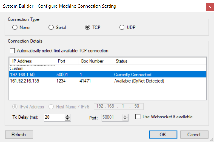
To establish a successful connection, select the job name (to connect to the trunk) or a gateway/bridge (to connect to a spur) in the tree, click ![]() Connection Settings, and select the Connection Type:
Connection Settings, and select the Connection Type:
The Connection Details section lists the available USB COM ports and shows the port status.
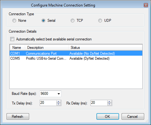
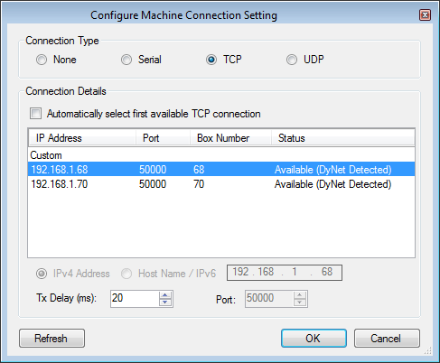
The Connection Details section lists the available EGs configured with TCP IP addresses, port numbers and box numbers and shows the port status. The default port number is 50000.
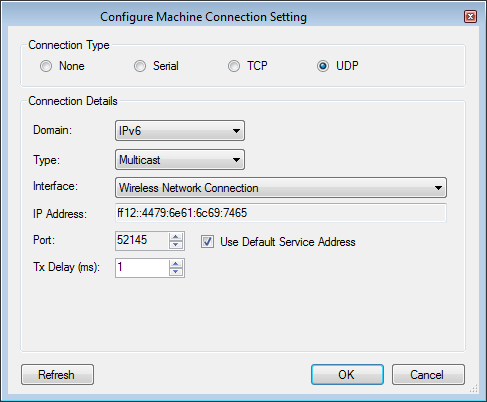
The Connection Details section allows you to select the Domain, Type, Interface, IP address and Port number. The default is IPv6 multicast service address: ff12:4479:6e61:6c69:7465, Port 52145.
| for security reasons, the UDP Multicast default service address is being deprecated. To connect to Ethernet devices, click the Insert Devices from Network icon and select Discover Network > Discover Devices over Ethernet (This will find Ethernet devices even when SB is disconnected). |
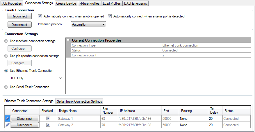
The Ethernet Trunk Connection Settings page lists the available EGs configured with TCP/IP addresses, port numbers and box numbers and shows the port status. The default port number is 50000. This connection is only available after EG commissioning is complete.
Adding an IPv4 port
If you want to create a TCP connection to the EG instead of using a serial connection or UDP IPv6 multicast connection, you can add a TCP IPv4 port and make the gateway into a server.
-
Plug in a PC Node to the USB port on your PC and then to the RS-485 port on the device.
-
Connect SB to the device via the RS-485 network serial port.
-
Click, the Port Editor tab.
-
Set Static IP to True.
-
Enter an IP address for the EG (e.g., 192.168.1.50).
-
Click
 Add and select
  IPv4 Port.
 -
Configure the IPv4 Port with the following settings:
Port Flags Port type
DyNet2
Connection
Trunk
Mode
Server
Area zero transmit
Disabled
Port Number
50001
Sign on at start up
Enabled
Protocol
TCP

-
Press F12 or click
 Save to Device.
 -
Click
 Send Device Reset.
 -
After the device reboots, reconnect SB with a TCP connection.
Connection status
You can connect your PC to any device in a single spur network; however, for multi-spur networks System Builder (SB) needs to know if it is physically connected to the trunk or to the spur to ensure that it can correctly address devices. In multi-spur networks the following icons in the tree show which part of the network SB is connected to:
-
 SB is currently connected to this trunk or spur
 -
 SB is connected at a level above this spur
 -
 SB is connected at a level below this trunk
 -
 SB is NOT currently connected to this trunk or spur

SB shows the connection status in the lower right corner: 

SB shows the connection status in the lower right corner: 
| SB can connect to a trunk or spur in the system without physically changing how the PC is plugged in. Check that the physical connection matches the view in the tree. Errors in address translation may occur in your system if you change configuration or add devices whilst being connected to a different level/bridge than intended. |
Creating a Site CA Certificate
The site CA certificate (Site Private Key) is created in SB and is then used to sign and upload a device site certificate to the PDDEG-S gateways and to Ethernet devices. When SB has a Site CA certificate, it shows a ![]() green lock icon at job level in the System and Building views.
green lock icon at job level in the System and Building views.
SB shows the same ![]() green lock icon next to a PDDEG-S or Ethernet device when a device site certificate has been uploaded. This enables SB/SM and Ethernet devices to securely connect to the PDDEG-S via TLS TCP.
green lock icon next to a PDDEG-S or Ethernet device when a device site certificate has been uploaded. This enables SB/SM and Ethernet devices to securely connect to the PDDEG-S via TLS TCP.
If the lock icon on an EG shows a ![]() warning icon, check the tooltip as it will indicate one of the following:
warning icon, check the tooltip as it will indicate one of the following:
-
Device site certificate is configured but site CA used to sign the device certificate is not found on this machine. System Builder will be unable to securely connect to this device. Ensure correct site CA certificate is imported into this machine with the Tools menu,
 Set Site CA Certificate option.
 -
Device site certificate is configured but doesn’t match Site CA configured in job. System Builder will be unable to securely connect to this device. An updated device site certificate should be signed and uploaded to the device.
|
-
Select Tools >
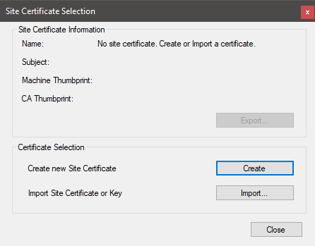
 Set Site CA Certificate to open the Site Certificate Selection window.
 -
If starting a new job, click the button to create a new site certificate.
-
After creating a new site certificate, you will be prompted to Export the Site Certificate and save it in a secure location.
-
For additional security when exporting the site certificate, you must enter a password. This password will be required by anyone importing the site certificate into another machine.
-
-
If someone has already started commissioning any of the devices and already created a site certificate, then they will need to export the certificate from their machine. You can then import the site certificate and enter the password into any machines used to commission or connect to secure Ethernet devices.
System Hardening
The proprietary DyNet communication over IP networks may or may not contain any additional security measures. Therefore, physical access to the system should be restricted to authorized persons only, and segregated from other Ethernet networks.
To mitigate the risk of unauthorized access to a system, it is important that during commissioning, site-specific information is stored securely and only shared with relevant project stakeholders.
System hardening must be performed on every system before handover to the customer. Ensure that you secure all system connections and interfaces as much as possible. To complete commissioning, the commissioning engineer must disable all connectivity except that required and remove default credentials.
-
Back up databases.
-
Install gateways and controllers in a secure enclosure/distribution board/room.
-
Make the data cabling physically inaccessible except to authorized persons, as much as possible.
-
Use a VLAN or separate cables to segregate the control network from corporate IP networks.
-
Use a secure connection or VPN where possible for connections to Integrated systems.
-
Delete unnecessary System Manager user accounts and carefully manage necessary accounts.
-
Delete unnecessary Ethernet gateways user accounts.
-
Enable CGI (only) user authentication on interfaces.
-
Implement LDAP + StartTLS for user authentication on relevant devices, where possible.
-
Remove unnecessary user permissions.
-
Implement complex user passwords in interfaces (8-12 Characters).
-
Implement complex user passwords in gateways (> 20 character fully random, that is not shared by any other gateway).
-
Disable UDP default multicast port.
-
Disable UDP default unicast port.
-
Disable WebSocket if not used.
-
Remove unnecessary protocols and disable unnecessary features such as FTP and Telnet.
-
Disable unnecessary ports.
-
Install security certificates in gateways to establish TLS TCP connections, where possible.
-
Install security certificates on the server/client machines to use HTTPS connections where possible.
-
Install 802.1X certificates to enable 802.1X (https://en.wikipedia.org/wiki/IEEE_802.1X)
For more information, refer to the Dynalite System Hardening Guide.